ORDER NO. ITD0203008C3 Projection Television TX-47P500HM TX-47P500HQ TX-47P500HZ TX-47P500X EURO-7VPChassis Specifications Power Source: 28-69 (PAL-B AUST.) TX-47P500HM/HQ/HZ: AC220-240V, 50/60Hz 13-57 (PAL-D, K) TX-47P500X: AC110-240V, 50/60Hz 13-62 (NTSC-M Japan) 14-69 (NTSC-M U.S.A.) S1-S20 (OSCAR) TX-47P500X: 228W S21-S41 (HYPER) 3.0W (Stand-by condition) 1-125 (U.S.A. CATV) Power Consumption: TX-47P500HM/HQ/HZ: 218W CATV Remote control Transmitter: 5A, 9A (AUST.
TX-47P500HM / TX-47P500HQ / TX-47P500HZ / TX-47P500X Headphones: Monitor OUT 3.5 mm Plug Aerial Impedance: Video out 1Vp-p 759 Audio out Approx. 0.5V 1k9 Accessories Supplied: 75 9 Unbalanced coaxial Remote Controller x 1 Video/Audio Terminals: AV1, 2, 3, 4 IN S-Video in "R6" Battery x 2 Y: 1.0 Vp-p 759 759 coaxial aerial plug C: 0.3Vp-p 759 DVD (Y/PB/PR) Video in Audio in 1 Vp-p 759 Design and Specifications are subject to change without notice. Approx. 0.
TX-47P500HM / TX-47P500HQ / TX-47P500HZ / TX-47P500X 14.1. Schematic Diagram Notes 67 14.12. LR, LG and LB-Board Schematic Diagram 78 14.2. A-Board (1 of 4) Schematic Diagram 68 14.13. M-Board Schematic Diagram 79 14.3. A-Board (2 of 4) Schematic Diagram 69 14.14. P-Board Schematic Diagram 80 14.4. A-Board (3 of 4) Schematic Diagram 70 14.15. SR, SG and SB-Board Schematic Diagram 81 14.5. A-Board (4 of 4) Schematic Diagram 71 14.16. U-Board Schematic Diagram 82 14.6.
TX-47P500HM / TX-47P500HQ / TX-47P500HZ / TX-47P500X 1 Safety Precautions 1.1. General Guide Lines 1. It is advisable to insert an isolation transformer in the AC supply before servicing a hot chassis. 2. When servicing, observe the original lead dress, especially the lead dress in the high voltage circuits. If a short circuit is found, replace all parts which have been overheated or damaged by the short circuit. 3.
TX-47P500HM / TX-47P500HQ / TX-47P500HZ / TX-47P500X 2 Chassis Board Layout Board-Name A-Board P-Board D-Board LR-Board LG-Board LB-Board H-Board U-Board M-Board DG-Board SR-Board SG-Board SB-Board Function Main Signal, Digital Converter Line Filter Deflection, High Voltage CRT Drive (R) CRT Drive (G) CRT Drive (B) Rear terminal MPU Front Terminal, Power Switch Digital Core VM Output (R) VM Output (G) VM Output (B) 5
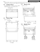
TX-47P500HM / TX-47P500HQ / TX-47P500HZ / TX-47P500X 3 Disassembly for Service This flowchart indicates disassembly items of the cabinet parts and circuit boards in order to find the items necessary for servicing, when reassembling, perform the procedures in the reverse order. 3.1.
TX-47P500HM / TX-47P500HQ / TX-47P500HZ / TX-47P500X Note: Board ground wires may have to be disconnected to disassemble some boards. All ground wires must be reconnected using jumper leads if necessary before power is applied to Receiver for service. 3.2. 3.4. Ornament Panel 1. Remove (2) screws. 1. The Ornament Panel is secured by (3) striker pins. Grip the Ornament Panel at the side corner pull to remove. 3.3. Speaker Grille Cabinet (Top) 1. Remove (11) Screws. 3.5. Speaker Ass´y 1.
TX-47P500HM / TX-47P500HQ / TX-47P500HZ / TX-47P500X 3.6. Screen 3.8. 1. Remove (14) screws. Rear Cover (Top) 1. Remove (4) screws. 2. Remove (2) screws. 3.9. 3.7. Mirror Rear Cover (Bottom) 1. Remove (18) screws. 2. Remove (1) screws. 1. Remove (4) screws. 2. Remove (8) screws.
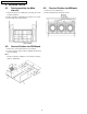
TX-47P500HM / TX-47P500HQ / TX-47P500HZ / TX-47P500X 3.10. Disassembly For CRT Removal 8. Note position of yoke with centering tabs and remove from defective CRT. To facilitate CRT replacement, the complete CRT mounting chassis does not need to be removed. 9. From the Top, remove (2) screws from the defective CRT. 1. Remove the Screen Frame Ass´y, Decorative Panel and the Bottom Rear Cover Ass´y. ( See Disassemble for Service ). 10.
TX-47P500HM / TX-47P500HQ / TX-47P500HZ / TX-47P500X 4 Service Hints 4.1. Service position for Main chassis 4.3. 1. Remove the Top Cabinet Ass´y. 2. Remove M-Board by removing (3) screws. 1. Remove the Rear Cover (Bottom) by removing (19) screws around its perimeter. 2. Remove lead wires and bundles from holders as necessary. 3. Pull out main chassis and stand it. 4.2. Service Position for M-Board Service Position for DG-Board 1. Remove the each circuit board from A or D-Board. 2.
TX-47P500HM / TX-47P500HQ / TX-47P500HZ / TX-47P500X 5 Self Check 1. Self-Check is used to automatically check the bus lines and hexadecimal code of the TV set. ) button on the customer controls at the front of the set, at the same 2. To get into the Self -Check mode press the down ( time pressing the HELP button on the remote control, and the screen will show : If the CCU ports have been checked and found to be incorrect or not located then “--” will appear in place of “O.K.”.
TX-47P500HM / TX-47P500HQ / TX-47P500HZ / TX-47P500X 6 Service Mode Function MPU controls the functions switching for each IICs through IIC bus in this chassis. The following setting and adjustment can be adjusted by remote control in Service Mode. 6.1. How to enter SERVICE 1 1. In sound menu, set BASS to MAX, and set TREBLE to MINIMUM. 2. Simultaneously press INDEX button on remote control and VOLUME DOWN button [ - ] on the TV set. 6.2. How to enter SERVICE 2 1. Set the channel to CH99. 2.
TX-47P500HM / TX-47P500HQ / TX-47P500HZ / TX-47P500X 6.3.
TX-47P500HM / TX-47P500HQ / TX-47P500HZ / TX-47P500X 14
TX-47P500HM / TX-47P500HQ / TX-47P500HZ / TX-47P500X 15
TX-47P500HM / TX-47P500HQ / TX-47P500HZ / TX-47P500X 7 CRT Set Up Caution: 7.3. Insure yoke plugs on the A-Board are reconnected before turning the Receiver ON to prevent damage to the horizontal output transistor and/or CRTs. 7.1. Optical Lens Focus Adjustment Note: This adjustment normally should not require resetting unless the lens has been replaced or adjustment has changed. Dynamic Focus Adjustment 1. Focus adjustments should be performed after 1 hour of aging. 1.
TX-47P500HM / TX-47P500HQ / TX-47P500HZ / TX-47P500X 7.4. Centering Magnet Adjustment 1. Receive a monoscope pattern. 2. Confirm that Coarse convergence data (Service mode1) for R,G and B is 0. 3. Set that Fine convergence data (Service mode1) is clear (no correction). 4. Set that V-Pos data (Service mode1) is [100]. 5. Set that H-Pos data (Service mode1) is [55]. 6. Set that H-Parallel data (Service mode1) is [8]. Procedure: 1. Cover the Red, Blue CRT lens, projecting Green only. 2.
TX-47P500HM / TX-47P500HQ / TX-47P500HZ / TX-47P500X 7.5. Alignment magnet Adjustment Preparation: 1. Receive an cross hatch pattern with dots (pincushion). 2. Loosen the centering magnets screws. 3. Position the longer tab of the four-pole magnet to 90 degrees (uncorrected position). 11. Receive an monoscope pattern. VM Coil with focus correction magnet 12. Cover the Red, Blue CRT lens, projecting Green only. 13.
TX-47P500HM / TX-47P500HQ / TX-47P500HZ / TX-47P500X 8 Deflection Adjustment Caution 8.1.3. 1. The following adjustment have to be carried out one with PAL signal (100i/50p) and with NTSC signal (60p/120i). V-Amp, V-Linear and V-Pos Adjustment 1. Adjust Vertical amplitude for 2.5 ± 0.1 division of a scale by V-Amp control. 2. Deflection adjustment need to set the Coarse/Fine Convergence to Zero Correction some time. 3.
TX-47P500HM / TX-47P500HQ / TX-47P500HZ / TX-47P500X 8.2. 8.2.1. PAL Progressive mode (50p) 8.3. Preparation 8.3.1. NTSC Progressive mode (60p) Preparation 1. Receive PAL monoscope pattern. 1. Receive NTSC monoscope pattern. 2. Copy the Data of PAL 100Hz mode (100i) to PAL Progressive mode (50p) 2. Set scan mode to Progressive. 3. Set scan mode to progressive. 4. Set the TV to Service Mode 1. 4. Set the Picture Menu to NORMAL. 5. Set the Data of Service Mode 1 as follow 3.
TX-47P500HM / TX-47P500HQ / TX-47P500HZ / TX-47P500X 8.3.3. V-Amp, V-Linear and V-Pos Adjustment 8.4. 8.4.1. 1. Adjust Vertical amplitude for 2.5 ± 0.1 division of a scale by V-Amp control. NTSC 120Hz mode (120i) Preparation 1. Receive PAL monoscope pattern. 2. Copy the Data of to NTSC Progressive mode (60p) to NTSC 120Hz mode (120i). 3. Set the Picture Menu to NORMAL. 4. Set scan mode to 120Hz. 5. Set the TV to Service Mode 1. 6.
TX-47P500HM / TX-47P500HQ / TX-47P500HZ / TX-47P500X 8.5. 8.5.1. 525p Deflection Adjustment / Confirmation V / H-Deflection confirmation 1. Receive 525p signal. 2. Confirm V / H-Deflection is normal. 8.5.2. H-Pos confirmation / Adjustment 1. Receive 525p signal. 2. Confirm H-Pos and if need, adjust H-Pos. 8.6. 8.6.1. 625p Deflection Adjustment / Confirmation V / H-Deflection confirmation 1. Receive 625p signal. 2. Confirm V / H-Deflection is normal 8.6.2. H-Pos confirmation / Adjustment 1.
TX-47P500HM / TX-47P500HQ / TX-47P500HZ / TX-47P500X 9 Adjustment Procedure 9.1. SECAM Black Level Adjustment Preparation Picture Menu: Dynamic AI: ON Adjustment 1. Receive SECAM white pattern. 2. Connect an oscilloscope to A44 pin 39(B-Y OUT) on A-Board. 3. Adjust SECAM B-Y so that H-blanking time and colour center are equal level. 4. Connect an oscilloscope to A44 pin 41(R-Y OUT) on A-Board. 5. Adjust SECAM R-Y so that H-blanking time and colour center are equal level. 6.
TX-47P500HM / TX-47P500HQ / TX-47P500HZ / TX-47P500X 9.2. Cut off Adjustment Preparation Picture Menu : Dynamic C Temp : Standard AI : ON P-NR : ON WB-B-G-ST1 : 255 High-RGB : 128 Low-RGB : 640 Cut off : A8 Scan Mode : 100Hz (PAL) G-Limit : 255 Screen VR : Full Counterclockwise B-Limit : 255 Adjustment 1. Receive a Black Level pattern. 2. Connect an oscilloscope to TPLG1 on LG-Board. 3. Adjust Sub Bright so that the waveform A is 200 ± 2V. 4. Connect an oscilloscope to TPLR1 on LR-Board. 5.
TX-47P500HM / TX-47P500HQ / TX-47P500HZ / TX-47P500X 9.3. Sub Contrast / G-Limit Adjustment Preparation Picture Menu : Dynamic C Temp : Standard AI : ON WB-B-G-ST1 : 255 High-RGB : 128 Low-RGB : 640 P-NR : ON G-Limit : 255 Scan Mode : 100Hz (PAL) Cut off Adjustment has been adjusted Adjustment 1. Receive a Cross Hatch pattern. 2. Connect an oscilloscope to TPLG1 on LG-Board. 3. Adjust Sub Contrast so that the waveform A is 150 ± 2V. 4.
TX-47P500HM / TX-47P500HQ / TX-47P500HZ / TX-47P500X 9.5. NTSC Tint Adjustment Preparation Picture Menu : Dynamic C Temp : Standard P-NR : ON Scan Mode : 100Hz (PAL) AI : ON Adjustment 1. Receive a Rainbow (NTSC 3.58Hz) pattern. 2. Connect an oscilloscope to TPLR1 on LR-Board. 3. Adjust Sub NTSC Tint so that the peak of level of waveform is similar to Fig. A. 4. Receive a Rainbow (NTSC 3.58Hz) pattern on both of Main and Sub picture. 5.
TX-47P500HM / TX-47P500HQ / TX-47P500HZ / TX-47P500X 9.7. Blue Focus / Gamma Adjustment Preparation Picture Menu : Dynamic C Temp : Standard WB-B-G-ST1 : 0 B-Limit : 255 AI : ON P-NR : ON Scan Mode : 100Hz (PAL) Adjustment 1. Set the White Balance Meter on Screen center. 2. Receive a Window pattern. 3. Set the Sub Contrast and High-B to Max. 4. It pushes and it makes a [HELP] key the project only of BLUE. 5. Adjust Blue Focus VR so that Y is 4.0 ± cd/m2 9.8.
TX-47P500HM / TX-47P500HQ / TX-47P500HZ / TX-47P500X 9.9. Sub Bright Adjustment Preparation Picture Menu : Dynamic C Temp : Dynamic P-NR : ON Scan Mode : 100Hz (PAL) AI : ON Cut off and White Balance Adjustment has been adjusted Adjustment 1. Set the White Balance Meter on Screen center. 2. Receive a PAL Window pattern. 3. Adjust Sub Bright so that the 7th paragraph shines faintly and the 8th paragraph does to the sinking style. 9.10.
TX-47P500HM / TX-47P500HQ / TX-47P500HZ / TX-47P500X 10 Convergence Adjustment The convergence adjustment is set separately for each 50/100Hz/ 60/100Hz input (NTSC, PAL/ SECAM). The following explanation uses the PAL mode as an example, since the same procedure applies to the convergence adjustment for NTSC mode. Adjust the convergence for each of the 50/100Hz and 60/120Hz inputs so that they are aligned with the other colours.
TX-47P500HM / TX-47P500HQ / TX-47P500HZ / TX-47P500X 10.2. Convergence Adjustment Procedure 1. Input a monoscope pattern of PAL. 2. Enter the Service Mode1. 3. Select the Coarse Convergence by pushing "RED" or "GREEN" buttons. Then push "YELLOW" button, and push Position and [N] buttons to set the data to zero. 4. Stick the Convergence Adjustment Sheet (PAL 50Hz) onto the screen. 5. Push the “YELLOW” or “BLUE” on the remote control, and enter the Coarse Convergence Adjustment mode. 10.
TX-47P500HM / TX-47P500HQ / TX-47P500HZ / TX-47P500X 10.3. Coarse Convergence Adjustment mode 10.3.1. Green Coarse Convergence Adjustment 10.3.1.1. Reparation Push the "SOUND" button, and select the Green Adjustment mode.Push the "2" button, and select the "Border and Cross" pattern.Push the "MUTE" button, and select the "Green" colour. 10.3.1.2. "G-SIZE (V)" adjustment Push the "TV/AV" buttons, and select the "G-SIZE (V)".
TX-47P500HM / TX-47P500HQ / TX-47P500HZ / TX-47P500X 10.3.1.3. "G-SIZE (H)" adjustment Push the "TV/AV" buttons, and select the "G-SIZE (H)".Push the "Volume up/down" buttons, and adjust the boarder line on either side of test pattern is aligned with the edge of the screen frame. 10.3.1.4. "G-LINEAR" adjustment Push the "TV/AV" buttons, and select the "G-LINEAR".Push the "Volume up/down" buttons, and adjust the "G-LINEAR" to become the following figure. 10.3.1.5.
TX-47P500HM / TX-47P500HQ / TX-47P500HZ / TX-47P500X 10.3.1.7. "G-CORNER" adjustment Push the "TV/AV" buttons, and select the "G-CORNER".Push the "Volume up/down" buttons, and adjust the "G-CORNER" to become the following figure. 10.3.1.8. "G-KEY" adjustment Push the "TV/AV" buttons, and select the "G-KEY".Push the "Channel up/down" buttons, and adjust the "G-KEY" refer to following figure. 10.3.1.9. "G-STATIC" adjustment Push the "TV/AV" buttons, and select the "G-STATIC".
TX-47P500HM / TX-47P500HQ / TX-47P500HZ / TX-47P500X 10.3.2. Red Coarse Convergence Adjustment 10.3.2.1. Reparation Push the "SOUND" button, and select the Red Adjustment mode.Push the "2" button, and select the "Border and Cross" pattern.Push the "MUTE" button, and select the "Yellow" colour.Push the "POSITION" button, and adjust the "R-STATIC" so that the Red color of pattern is aligned with Green colour of pattern. 10.3.2.2. "R-SKEW (V)" adjustment Push the "TV/AV" buttons, and select the "R-SKEW".
TX-47P500HM / TX-47P500HQ / TX-47P500HZ / TX-47P500X 10.3.2.6. "R-LINEAR" adjustment Push the "TV/AV" buttons, and select the "R-LINEAR".Push the "Volume up/down" buttons, and adjust the "R-LINEAR". (Refer to Fig. C.) 10.3.2.7. "R-PIN (V)" adjustment Push the "TV/AV" buttons, and select the "R-PIN".Push the "Channel up/down" buttons, and adjust the "R-PIN (V)". (Refer to Fig. D.) 10.3.2.8. "R-PIN (H)" adjustment Push the "TV/AV" buttons, and select the "R-PIN".
TX-47P500HM / TX-47P500HQ / TX-47P500HZ / TX-47P500X 10.3.3.6. "B-LINEAR" adjustment Push the "TV/AV" buttons, and select the "B-LINEAR".Push the "Volume up/down" buttons, and adjust the "B-LINEAR". (Refer to Fig. C.) 10.3.3.7. "B-PIN (V)" adjustment Push the "TV/AV" buttons, and select the "B-PIN".Push the "Channel up/down" buttons, and adjust the "B-PIN (V)" (Refer to Fig. D.) 10.3.3.8. "B-PIN (H)" adjustment Push the "TV/AV" buttons, and select the "B-PIN".
TX-47P500HM / TX-47P500HQ / TX-47P500HZ / TX-47P500X 10.4. Fine Convergence Adjustment 8. Use the Position Buttons to adjust each point so that the Green Crosshatch Pattern is aligned with the vertical and horizontal lines of the Convergence Adjustment Sheet. 10.4.1. Green Convergence Adjustment 1. Select the "G-LINE CURSOR" mode by pushing "TV/AV" button on the remote control 9. Push the "MULTI PIP" and with from "G-EASY DATA" to "G-EASY CURSOR". 10. Repeat step 7~9 to adjust the 9 adjustment points.
TX-47P500HM / TX-47P500HQ / TX-47P500HZ / TX-47P500X 10.4.2. Red Convergence Adjustment 1. Push the "MUTE" button twice and change to the Red Adjustment of Yellow Colour. 2. Repeat the same steps described for the Green Conv.Adj. in 1~16 to perform the Red Convergence Adjustment. 3. To store the data after the Red Convergence Adjustment has been completed, push the "MAIN MENU" button and then the "N" button. 10.4.3. Blue Convergence Adjustment 1.
TX-47P500HM / TX-47P500HQ / TX-47P500HZ / TX-47P500X Fine Convergence Control Chart 39
TX-47P500HM / TX-47P500HQ / TX-47P500HZ / TX-47P500X 40
TX-47P500HM / TX-47P500HQ / TX-47P500HZ / TX-47P500X 11 Location of Lead Wiring 41
TX-47P500HM / TX-47P500HQ / TX-47P500HZ / TX-47P500X INSERTION OF CONNECTOR LR1, LR2, LG1, LG2, LG3, LG4, LG5, LG6, LG7, LB1, LB2, LRGND1, LGGND1, LBGND1 NOTICE FOR WORE DRESSING 1. Confirm that the lead line isn’t hitting the metallic part of the neck print after CRT neck print (R, G, B) insertion. 2. It decides to be permitted to insert the lead line (R, G, B) of the VM coil wherever of LG5, LG6, LG7 of the LG print. 3. It decides to be permitted to insert G, B of the DY lead in either.
TX-47P500HM / TX-47P500HQ / TX-47P500HZ / TX-47P500X The Anode Lead 1. It inserts Anode lead tip in the back to FBT (the fly background transformer), and it makes turn on the right and it locks it. (Three insertion positions are free). 2. Secure a safe space distance from the circumference part by equal to or more than 10 millimeters. Attention 1. There is not sagging in Clamper -the D30 coupler pipe. 2.
TX-47P500HM / TX-47P500HQ / TX-47P500HZ / TX-47P500X INSERTION OF CONNECTOR A9, A21, A22, A23, A25, A26, Anode distributor (R, G, B, FBT), D5, DY (R, G, B), CY (R, G, B), D30, P1, P2, P4, Focus pack (Red) NOTICE FOR WIRE DRESSING 1. After insert R, G, B on CRT-print, confirm that wire should not touch to material parts of CRT-print.
TX-47P500HM / TX-47P500HQ / TX-47P500HZ / TX-47P500X 12 Conductor Views 12.1.
TX-47P500HM / TX-47P500HQ / TX-47P500HZ / TX-47P500X A Parts Location Parts Location A-BOARD (FOIL SIDE) IC IC051 IC052 IC501 IC1104 IC1105 IC1108 IC1251 IC1252 IC1315 IC2001 IC2301 IC2302 IC2705 IC2706 IC2707 IC2708 IC2709 IC2710 IC3001 IC3002 IC3004 IC3005 IC7101 IC7102 IC7105 IC7108 IC7109 IC7110 D-6 E-5 G-2 C-4 C-5 A-1 D-4 B-4 D-3 E-4 C-6 A-3 C-1 A-1 B-1 C-2 C-1 F-4 F-5 G-3 F-2 F-2 F-2 D-1 E-2 F-2 F-1 E-2 IC7121 IC7702 IC7703 IC9351 D-2 B-4 C-3 C-2 TRANSISTOR Q001 Q002 Q051 Q052 Q460 Q462 Q463 Q
TX-47P500HM / TX-47P500HQ / TX-47P500HZ / TX-47P500X A-BOARD (COMPONENT SIDE) TZTNP020GFV 6 5 4 3 2 1 A B C D E 47 F G H
TX-47P500HM / TX-47P500HQ / TX-47P500HZ / TX-47P500X 12.2.
TX-47P500HM / TX-47P500HQ / TX-47P500HZ / TX-47P500X D Parts Location Parts Location D-BOARD (FOIL SIDE) IC TP IC451 IC801 IC808 IC810 IC7001 IC7002 IC9601 G-5 B-2 C-3 B-5 C-5 E-5 F-4 TRANSISTOR Q451 Q551 Q552 Q553 Q554 Q555 Q556 Q557 Q701 Q805 Q849 Q854 Q7001 Q7002 Q7003 Q7004 Q9601 Q9602 Q9603 G-5 F-1 G-4 F-4 F-4 D-3 F-1 D-3 D-4 A-1 C-4 B-6 D-6 C-6 B-5 B-5 E-1 D-2 E-1 TP10 TP11 TP12 TP13 TP14 TP15 TP16 TP17 TP18 TP19 TP20 TP21 TP22 TP23 TP24 TP25 TP26 TP27 TP28 TP29 TP30 TP31 TP32 TP33 TP34 TP35
TX-47P500HM / TX-47P500HQ / TX-47P500HZ / TX-47P500X 6 D-BOARD (FOIL SIDE) TZTNP010GFV (TX-47P500HQ/HM) TZTNP010GHV (TX-47P500HZ) TZTNP010GJV (TX-47P500X) 5 4 3 2 1 A B C D E 50 F G H
TX-47P500HM / TX-47P500HQ / TX-47P500HZ / TX-47P500X 12.3.
TX-47P500HM / TX-47P500HQ / TX-47P500HZ / TX-47P500X 12.4.
TX-47P500HM / TX-47P500HQ / TX-47P500HZ / TX-47P500X 12.5.
TX-47P500HM / TX-47P500HQ / TX-47P500HZ / TX-47P500X 12.6.
TX-47P500HM / TX-47P500HQ / TX-47P500HZ / TX-47P500X 12.7.
TX-47P500HM / TX-47P500HQ / TX-47P500HZ / TX-47P500X 12.8.
TX-47P500HM / TX-47P500HQ / TX-47P500HZ / TX-47P500X 12.9.
TX-47P500HM / TX-47P500HQ / TX-47P500HZ / TX-47P500X 58
TX-47P500HM / TX-47P500HQ / TX-47P500HZ / TX-47P500X 13 Block Diagram 13.1.
TX-47P500HM / TX-47P500HQ / TX-47P500HZ / TX-47P500X 13.2.
TX-47P500HM / TX-47P500HQ / TX-47P500HZ / TX-47P500X 61
TX-47P500HM / TX-47P500HQ / TX-47P500HZ / TX-47P500X 13.3.
TX-47P500HM / TX-47P500HQ / TX-47P500HZ / TX-47P500X 63
TX-47P500HM / TX-47P500HQ / TX-47P500HZ / TX-47P500X 64
TX-47P500HM / TX-47P500HQ / TX-47P500HZ / TX-47P500X 65
TX-47P500HM / TX-47P500HQ / TX-47P500HZ / TX-47P500X 13.4.
TX-47P500HM / TX-47P500HQ / TX-47P500HZ / TX-47P500X 14 Schematic Diagram 14.1.
TX-47P500HM / TX-47P500HQ / TX-47P500HZ / TX-47P500X 14.2.
TX-47P500HM / TX-47P500HQ / TX-47P500HZ / TX-47P500X 14.3.
TX-47P500HM / TX-47P500HQ / TX-47P500HZ / TX-47P500X 14.4.
TX-47P500HM / TX-47P500HQ / TX-47P500HZ / TX-47P500X 14.5.
TX-47P500HM / TX-47P500HQ / TX-47P500HZ / TX-47P500X 14.6.
TX-47P500HM / TX-47P500HQ / TX-47P500HZ / TX-47P500X 14.7.
TX-47P500HM / TX-47P500HQ / TX-47P500HZ / TX-47P500X 14.8.
TX-47P500HM / TX-47P500HQ / TX-47P500HZ / TX-47P500X 14.9.
TX-47P500HM / TX-47P500HQ / TX-47P500HZ / TX-47P500X 14.10.
TX-47P500HM / TX-47P500HQ / TX-47P500HZ / TX-47P500X 14.11.
TX-47P500HM / TX-47P500HQ / TX-47P500HZ / TX-47P500X 14.12.
TX-47P500HM / TX-47P500HQ / TX-47P500HZ / TX-47P500X 14.13.
TX-47P500HM / TX-47P500HQ / TX-47P500HZ / TX-47P500X 14.14.
TX-47P500HM / TX-47P500HQ / TX-47P500HZ / TX-47P500X 14.15.
TX-47P500HM / TX-47P500HQ / TX-47P500HZ / TX-47P500X 14.16.
TX-47P500HM / TX-47P500HQ / TX-47P500HZ / TX-47P500X 15 Parts location Note: The number on mechanical parts indicates Ref. No.
TX-47P500HM / TX-47P500HQ / TX-47P500HZ / TX-47P500X 84
TX-47P500HM / TX-47P500HQ / TX-47P500HZ / TX-47P500X 16 Mechanical Replacement Parts List Ref. No. Part No.
TX-47P500HM / TX-47P500HQ / TX-47P500HZ / TX-47P500X 17 Electrical Replacement Parts List 17.1.
TX-47P500HM / TX-47P500HQ / TX-47P500HZ / TX-47P500X 17.2. Electrical Replacement Parts List Ref. No. Part No.
TX-47P500HM / TX-47P500HQ / TX-47P500HZ / TX-47P500X Ref. No. Part No.
TX-47P500HM / TX-47P500HQ / TX-47P500HZ / TX-47P500X Ref. No. Part No.
TX-47P500HM / TX-47P500HQ / TX-47P500HZ / TX-47P500X Ref. No.
TX-47P500HM / TX-47P500HQ / TX-47P500HZ / TX-47P500X Ref. No. Part No.
TX-47P500HM / TX-47P500HQ / TX-47P500HZ / TX-47P500X Ref. No. Part No.
TX-47P500HM / TX-47P500HQ / TX-47P500HZ / TX-47P500X Ref. No. Part No.
TX-47P500HM / TX-47P500HQ / TX-47P500HZ / TX-47P500X Ref. No. Part No.
TX-47P500HM / TX-47P500HQ / TX-47P500HZ / TX-47P500X Ref. No. Part No.
TX-47P500HM / TX-47P500HQ / TX-47P500HZ / TX-47P500X Ref. No. Part No.
TX-47P500HM / TX-47P500HQ / TX-47P500HZ / TX-47P500X Ref. No. Part No.
TX-47P500HM / TX-47P500HQ / TX-47P500HZ / TX-47P500X Ref. No. Part No.