Operating Instructions Touch Panel Model No. TY-TP42P30K TY-TP50P30K TY-TP60P30K TY-TP65P30K Before connecting, operating or adjusting this product, please read these instructions completely. Please keep this manual for future reference.
Contents Ŷ Precautions with regard to setting up ........................2 Ŷ Maintenance .............................................................3 Ŷ Components .............................................................4 Ŷ Touch Panel Assembly ..............................................5 Ŷ Mounting Touch Panel ...............................................6 Ŷ Connection with Computer ........................................8 Ŷ Operating Conditions.................................................
Maintenance Setup location Places where the touch panel should not be setup include: • Locations exposed to direct sunlight, and locations near powerful light sources (The equipment is an optical touch panel utilizing infrared rays and may function incorrectly when adversely affected.
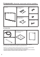
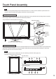
Components (Check the components and their quantities.) Touch panel (1) Mounting bracket A (for top side) Mounting bracket A (for bottom side) Mounting bracket B (4) Mounting screw A (8) Mounting screw B (8) (2) (2) Accessories USB extension cable (1) CD-ROM • Operating Instructions • Driver software Touch pen (2) (1) Operating Instructions Ŷ Illustrations are conceptual views and may differ in shape from the actual equipment.
Touch Panel Assembly Note • Place the touch panel making its front surface face down on a clean cloth or blanket to prevent the front surface of the touch panel from getting scratched or dirty during work. Mounting in horizontal posture Attach the mounting brackets A (for top and bottom sides) to the touch panel with the mounting screws A (2 each). See the ¿gure below for the screw holes of attachment positions. The procedure for vertical posture is the same.
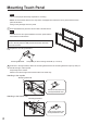
Mounting Touch Panel Notes • Two or more people are always required for mounting. • Never mount the main device in the way that is overlapped from above the touch panel while the touch panel is laid down. Doing so may damage the touch panel. 1 Fit the assembled touch panel from the front side of the main device. Note • There should not be a space between the touch panel and the front surface of main device. The procedure for vertical posture is the same.
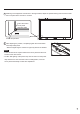
4 Referring to the alignment mark shown in the figure below, adjust the position seeing from the front so that the touch panel does not lean to one side. End of the screen Touch panel alignment mark Power lamp window 5 After adjusting the position, completely tighten the screws which were temporarily fixed. • Note that tightening the screws too tight may deform the bracket. Notes • There should not be a space between the touch panel and the front surface of the main device.
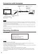
Connection with Computer USB connector type A (Female) Touch panel USB connector type A (Male) Connect to the USB port on your computer. Computer Main device USB connector type A (Male) To connect to your computer, see the instruction manual of the main device.
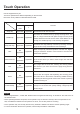
Touch Operation Use the supplied touch pen. The touch operations are different depending on the OS used. Dual touch is not possible on Windows XP and Vista. Windows XP/ Vista Single tap Applicable Function 7 Applicable Functions as a left click of mouse. Functions as a double-click by quickly touching twice. The Double tap Applicable Applicable pen or a finger should be set apart enough from the panel window before the second touch is made.
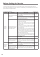
Before Calling for Service If you think the touch panel is broken or if it is not operating correctly, check the following before calling for service. When using Windows XP or Vista, refer also to “Troubleshooting” of the installation manual of the touch panel included in the supplied CD-ROM. For Windows XP, Vista and 7 Problem *1 Windows 7 only Check point Action to take Check that the USB cable is connected.
Problem Check point Action to take Page This equipment is a touch panel using infrared rays. Incident light containing infrared rays may hinder operation of the touch panel. Sunlight: It is not a problem as long as the infrared transmissive part of the touch panel is not directly exposed to sunlight.
Problem The touched point is displaced Check point Has calibration been performed? *1 Action to take Page Perform calibration in “General” of “Tablet PC Settings” of the Control Panel. For more information, see the help information of Windows. – If the touch panel was removed and mounted again, the mounting position may not be the same as the previous one, and thus the touching position and cursor position may not match.
Speci¿cations Model Number TY-TP42P30K TY-TP50P30K Power source Type TY-TP65P30K Touch Panel Voltage +5V DC±10% Electric current +5V DC Max. 500 mA Supply method From USB bus Detection system Panel window Detection range Touch Panel TY-TP60P30K Infrared ray interruption detection 934.1 mm (W) × 524.1 mm (H) 1124.1 mm (W) × 638.1 mm (H) 1348.1 mm (W) × 766.1 mm (H) 1468.1 mm (W) × 839.
External Dimensions External Dimensions Table of external dimensions (Unit: mm) A 42V 50V 60V 65V A 1028.2 1218.2 1442.2 1562.2 B 618.2 732.2 860.2 933.2 C 621.4 735.4 863.4 936.4 79.2 47 *(89) 47 (Unit: mm) 12 47 B C * The dimensions may vary depending on the device to be mounted to or the status of tightening. 47 *(89) 79.2 Drawing of Screw Holes (Mounting in vertical posture) • Refer to page 5 for 42V.
Customer’s Record The model number and serial number of this product can be found on its bottom side. You should note this serial number in the space provided below and retain this book, plus your purchase receipt, as a permanent record of your purchase to aid in identi¿cation in the event of theft or loss, and for Warranty Service purposes. Warranty conditions are managed by distributors to meet the standards set by each country. For details, contact your dealer where you made your purchase.