
Operating Instructions - Language - English


7
This Manual describes handling methods when installing this product into plasma displays made by our company,
and use with multiple screens.
The form of the terminal board will differ depending on the size of the display.
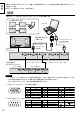
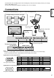
Connections
AUDIO
SERIAL
PC INSERIAL OUTPC1
INOUT
AUDIO
SERIAL
PC INSERIAL OUTPC1
INOUT
Computer
PC cable
D-sub 15p
RS-232C straight cable
D-sub 9p
To other Plasma display
PC1 IN terminal SERIAL terminal
Conversion adapter
(if necessary)
Notes:
• To enable use with multiple screens, multi-screen setting must be performed for each plasma display.
• Read the Operating Instructions supplied with the Plasma display for the details.
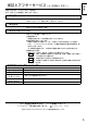
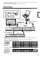
Connect 4 or 9 plasma displays in sequence, as shown in the diagram below.
Example showing connection of four units
RS-232C straight cable
PC cable
Signal Names for D-sub 15p Connector
Pin Layout for PC1 Terminal
Pin No.
1
2
3
4
5
Pin No.
6
7
8
9
10
Pin No.
11
12
13
14
15
Signal Name
R
G
B
GND (Ground)
GND (Ground)
Signal Name
GND (Ground)
GND (Ground)
GND (Ground)
NC (not connected)
GND (Ground)
Signal Name
GND (Ground)
SDA
HD/SYNC
VD
SCL
1
678
3
9
45
10
1514131211
2
Pin layout for SERIAL OUT Terminal
1
2
3
4
5
6
7
8
9
NC
RXD
TXD
Non use
GND
Non use NC
Shorted
9876
53214
Signal Names for D-sub 9p Connector
English