® Operating Instructions Touch Panel Model No. TY-TP42P8-S TY-TP50P8-S Before connecting, operating or adjusting this product, please read these instructions completely. Please keep this manual for future reference.
Table of Contents Warnings and precautions ........................................................ 3 Warnings ......................................................................... 3 Precautions ..................................................................... 3 Cautions when in use ...................................................... 4 Setup location ................................................................. 4 Maintenance ...................................................................
Warnings and precautions Warnings Do not allow the equipment to get wet. • If liquid splashes onto the equipment, wipe off with a dry cloth. In the unlikely event that liquid gets inside the product, unplug the USB cable and contact your dealer. Using the product with liquid still inside may cause a fire, electric shock or malfunction. Do not disassemble or modify the equipment. • Doing so may cause a fire, electric shock or malfunction.
Warnings and precautions Cautions when in use Always keep the touch panel clean • This optical touch panel utilizes infrared rays and may operate incorrectly if the infrared transmissive part becomes soiled. Use a soft dry cloth to clean the infrared transmissive part once every day. Use a power supply within the rated voltage range • Be sure that the power supply used conforms to the rated voltage. Use with a power supply exceeding the rating may cause incorrect operation or malfunction.
Warnings and precautions Maintenance ∗Be sure to unplug the USB cable before cleaning the equipment. Clean the inside of the equipment once a year. • The equipment is of semi-sealed construction, so dust may eventually accumulate inside. This may cause poor operation due to a reduction in the level of infrared light available for touch detection. Cleaning frequency will vary depending on the setup location; if in doubt consult the dealer from whom you purchased the equipment.
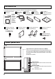
Accessories Check that all accessories are included. Quantities are indicated in parentheses. Operating Instruction Books (9) • English • French • German • Spanish • Japanese • Italiano • Chinese • Russian • Ukrainian Mounting screws [A] for Mounting brackets [A, B] TY-TP42P8-S (8) TY-TP50P8-S (10) USB cable (1) Length: 2 m (6.
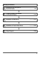
Setup procedure 1 Attachment of the touch panel to the plasma display ................P 8 2 Connection between the computer and the plasma display ..............P 10 3 Installation of USB Driver .............. P 11 4 Installation of Touch Panel Driver ..............P 21 5 Setup Program ..............
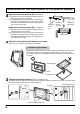
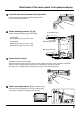
Attachment of the touch panel to the plasma display 1 Attach the mounting bracket. [A] (TY-TP42P8-S) (1) Orientate the mounting bracket [A] so that the side lined with cushion faces the touch panel. (2) During attachment of the touch panel to the display, lift the bracket to its highest point so that it does not strike the display and tentatively fasten to the upper part of 2 points to the left and right. Mounting Screw [A] Attach the mounting bracket.
Attachment of the touch panel to the plasma display 4 Lower the tentatively fastened mounting bracket. Loosen the tentatively fastened bracket mounting screws, and lower the mounting bracket. 5 Fasten mounting brackets. [A], [B] TY-TP50P8-S Only Fasten mounting brackets [A], [B] to the display.
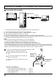
Connection between the computer and plasma display 1 Connection with computer USB USB connector USB cable Plasma Display (Rear view) Pen Computer OFF ON Touch Panel ∗ Check that the USB power supply of the computer being used is rated at 500 mA. (1) (2) (3) (4) (5) Connect the plasma display and computer with the VGA cable. Turn on power in the following sequence: 1: Plasma Display, 2: Computer. Switch the plasma display input signal to the computer.
Installation of the USB Driver Function The control software provides the following functionality. • Supplies a software interface for application programs that simulates the output of a mouse. This is achieved by converting touch panel output data into that which is compatible with the protocol used by the Microsoft serial mouse input. This makes it possible to operate existing applications and develop new applications employing the touch panel as if it were a mouse.
Installation of the USB Driver In case of Windows 98 SE Install USB Driver First, PC is started, and then Windows is started. The CD-ROM with USB driver software is inserted into the CD-ROM drive. Next, touch panel and PC are connected with a USB cable. (see page 10) When a USB cable is connected, “Add New Hardware Wizard” is indicated. 1 Click on this button. 2 Next, choose this item. 3 Click on this button. 4 Next, choose this CD-ROM drive. 5 Click on this button.
Installation of the USB Driver Setup is completed when all the files of the driver are copied. 7 Click to close this wizard. 8 The new hardware window is displayed again, and the driver for the assumed COM port is installed. COM port number is confirmed with “Device Manager” [Settings] [Control Panel] 1 Click on [Start] Double-click on “the system” icon of the control panel, and open the properties of the system. The properties of the system are opened. 2 Then click on the “Device Manager” tab.
Installation of the USB Driver In case of Windows ME In caseUSB of Windows Install Driver ME First, PC is started, and then Windows is started. The CD-ROM with USB driver software is inserted into the CD-ROM drive. Next, touch panel and PC are connected with a USB cable. (see page 10) When a USB cable is connected, it is recognized as a new hardware, and a message is indicated. 1 Choose “Automatic search for a better driver [Recommended]”. 2 Click on this button.
Installation of the USB Driver COM port number is confirmed with “Device Manager” [Settings] [Control Panel] 1 Click on [Start] Double-click on “the system” icon of the control panel, and open the properties of the system. 2 The properties of the system opens. Next, click on the “Device Manager” tab. 3 Double-click “Ports [COM&LPT]”. Confirm that “USB-Serial for Touch Panel V2 (COMx)” is found in “Ports [COM&LPT]”. (COMx) is the COM port number for using a touch panel.
Installation of the USB Driver In case of Windows 2000 Install USB Driver First, PC is started, and then Windows is started. The CD-ROM with USB driver software is inserted into the CD-ROM drive. Next, touch panel and PC are connected with a USB cable. (see page 10) When a USB cable is connected, it is recognized as a new hardware, and a message is indicated. Setup Wizard will start. 1 Click on this button. “Install Hardware Device Drivers” is indicated. 2 Choose this item. 3 Click on this button.
Installation of the USB Driver “Driver Files Search Results” is indicated. 6 Click on this button. Driver software is set up, and “Completing the Found New Hardware Wizard” is indicated. 7 Click Finish to close this wizard. 8 It is recognized as new hardware once again, and the screen on the left is displayed. COM port number is confirmed with “Device Manager” [Settings] [Control Panel] 1 Click on [Start] Double-click on “the system” icon of the control panel, and open the properties of the system.
Installation of the USB Driver In case of Windows XP Install USB Driver First, PC is started, and then Windows is started. The CD-ROM with USB driver software is inserted into the CD-ROM drive. Next, touch panel and PC are connected with a USB cable. (see page 10) When a USB cable is connected, the wizard of the driver setup starts. 1 Click on this button. Next, though the following warning message is indicated, there is no problem. 2 Click on this button. A driver file is copied and set up.
Installation of the USB Driver COM port number is confirmed with “Device Manager” [Settings] [Control Panel] 1 Click on [Start] Double-click on “the system” icon of the control panel, and open the properties of the system. 2 The properties of the system opens. Next click on the “Hardware” tab. Then click on the “Device Manager” button. 3 Double-click “Ports [COM&LPT]”. Confirm that “USBSerial for Touch Panel V2 (COMx)” is found in “Ports [COM&LPT]”. (COMx) is the COM port number for using a touch panel.
Installation of the USB Driver About the COM port When it is set up, the USB driver is recognized as a COM port of the PC. Specify this COM number when you don't use an automatic connection. The setup number varies in the use environment of the PC. Notes for Installation of USB driver (Windows 2000/XP) After the installation of the driver is completed, a new hardware wizard will not be displayed even if a USB cable is re-connected to the PC.
Installation of the Touch Panel Driver Install Touch Panel Driver The CD-ROM contains two different types of control software installers (one for Windows 98SE and Windows ME, and one for Windows 2000 and Windows XP). Start the set-up file corresponding to the OS you are using. OS Windows 98SE Windows ME Windows 2000 Windows XP CD-ROM (Installer) \English\Win9x_me\setup.exe Note: \English\Win2k_xp\setup.
Uninstallation of the Touch Panel Driver Delete “tpdrv” from the “Add/Remove Programs” of the “Control Panel”. In case of Windows 2000 (1) Click on [Start] [Settings] [Control Panel] (2) Double-click on [Add or delete applications]. (3) Click on the [Uninstall] tab. (4) Select “tpdrv” and click on the [Change and delete] button. (5) The file delete confirmation screen will be displayed. Click the [Yes] button. Uninstall will begin.
Setup program The setup program is to set communication ports and various operation modes and to carry out calibration or so on. Performing setup in the initial state saves the modified contents in “tpdrv.ini” setting file in “C:\Program Files\tpdrv” folder. Those contents are still valid at the time of the next startup. Setup of a basic Mode (see page 24) Pressing any button displays the setting window relative to that item to permit changes in set values.
Setup program Setup of basic settings This sets the COM port of connecting PC. The port being used for connection with the touch panel is selected. Communication Port When “Auto connect” is chosen, driver software detects it automatically, and it is set up. If it isn't possible to connect automatically, choose a connecting port. Connecting port number will vary depending upon the environment of PC. Calibration Mode (1) Normal Please select this mode when you caliblate normally.
Setup program Palm Touch (1) Off Please select this mode in case of touching display by finger or touch pen. (2) On Please select this mode in case of touching display by plam. Setup of Touch Pen ID ID of the optional touch pen is selected on the touch panel side. (1) ID Prohibition Regardless of the ID number, the signal is accepted. (2) ID No.1 - 4 Only the signal of the optional touch pen with the same ID is accepted.
Setup program Calibration Mode Pressing the [Calibration] button on the main window activates the calibration screen to carry out calibration of the detection of the Touch Panel and PC (in order to place the mouse cursor at the touched position). Briefly touch the center of the target displayed on the screen in order as they appear. Target is displayed in the order of upper left, bottom left, and upper right. To stop calibration, press any key on the keyboard.
Setup program Calibration Mode Touch on the center of the target. (To terminate, press any key) Touch on the center of the target.
Setup program Calibration Mode In case of special setting ∗ Calibration Screen is indicated in order as follows. To continue the calibration, click on the mouse.
Setup program Calibration Mode Left click on upper left corner of the display. (To terminate, press any key) Left click on lower right corner of the display.
Setup program Calibration Mode Can you see three targets within the display area? Yes Left click No Right click (To terminate, press any key) Touch on the center of the target.
Setup program Calibration Mode Touch on the center of the target. (To terminate, press any key) Touch on the center of the target.
Setup program User Setting The following window is displayed by pushing the user setting button of the Touch Panel setting program menu. Click Mode (See next page) Double click Time Time interval when double-clicking is set up. Time between the first touch and the second touch is set. When the second touch is performed within the set time, it is recognized as double click. Available time settings are 0.2 to 1.0 seconds within the interval of 0.2 seconds.
Setup program Click Mode Drag Touching the touch panel with your finger corresponds to the holding down operation of the left mouse button. Release of your finger from the touch panel corresponds to the release operation from the left mouse button. Therefore at the time of releasing the finger from the touch panel, click event occurs. In addition, when moving the finger, the mouse cursor follows the movement so that the drag operation is made possible.
Troubleshooting Before requesting repairs Symptom Please check the following points. Check No response at all to input Check the USB cable Check that the USB cable is securely connected. Check extraneous light Check whether there is (or might be) any equipment in the surrounding area that uses a powerful light source or infrared light. The touch panel is an optic type that uses infrared light. Extraneous light containing infrared radiation may interfere with operation.
Specifications Model Number Type Power Source Voltage Electric current Supply system Touch Panel Detection system Panel window (W × H) Detection range (W × H) Effective detection range Resolution (W × H) Detection pitch Output system Number of optic elements (W × H) Optic element pitch (W × H) Minimum stylus size (W × H) Touch pen USB Interface (USB 1.
External dimensions TY-TP42P8-S 63.9 (2.5) Specifications 1,073 (42.2) 63.9 (2.5) 63.9 (2.5) 945.2 (37.2) External dimensions TY-TP50P8-S 63.9 (2.5) 138 (5.4) 797 (31.4) 138 (5.4) 35.5 (1.4) 63.9 (2.5) 25.5 (1.0) 659 (25.9) 518 (20.4) Unit: mm (Inch) 61 (2.4) 8 (0.3) 1,257 (49.5) 63.9 (2.5) 63.9 (2.5) 1,106 (43.5) 230 (9.1) 797 (31.4) 230 (9.1) 35.5 (1.4) 63.9 (2.5) 25.5 (1.0) 773 (30.4) 645.2 (25.4) Unit: mm (Inch) 61 (2.4) 8 (0.