
Operating Instructions


1.1.3 Bus wiring example
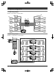
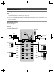
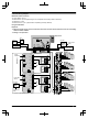
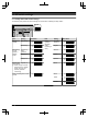
Example 2: 32 call buttons on the lobby station/6 lobby stations
D D
F
#8
#7
#6
#5
#4
#3
#2
#1
E
B
H
A
C
#1 #2 #3 #4 #5 #6
C
G
1.1.4 System devices
No. Item Star wiring Bus wiring
A Lobby station (VL-VM series) Up to 1 Up to 6
B
Main monitor
*1
,
*2
Up to 32 (depending on the composition of the lobby station’s
modules)
C
Power supply unit (VL-PS240) The number of required power supply units differs depending on the
number of devices used.
D Power supply unit (VL-PS2410)
The number of required power supply units differs depending on the
number of devices used.
E Distributor (VL-VM701) – Up to 8
F Extension box (VL-V703) – Up to 1
G
K-IN
connection device (example:
access controller and/or open
door sensor, etc.)
Up to 2 Up to 2
H Electric lock 1 per lobby station 1 per lobby station
*1 Refer to the installation and power supply unit information in the Installation and Operating Instructions on the
Panasonic Web site.
*2 VL-MV10 and VL-MWD501 support door bells. For VL-MWD501, a sound is played when the door bell is pressed,
but “
Doorphone unavailable” is displayed on the screen (this is normal).