
Operating Instructions


2.1 Wiring Connections
2.1.1 Wiring schematics
Note:
R Refer to the power supply unit information in the Installation and Operating Instructions on the Panasonic Web
site for information about connections for power supply units.
R See "3.1.1 Lobby station DIP switch settings" for information about lobby station DIP switch settings.
R See "3.1.2 Distributor DIP switch settings" for information about distributor DIP switches when using bus wiring.
R Insert
the wires fully into the connection terminals. After inserting the wires, pull slightly on each wire to make sure
it is firmly connected.
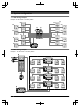
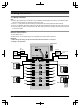
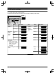
2.1.1.1 Star wiring example
Maximum number of devices
R Lobby station: up to 1
R Main monitor: up to 32 (depending on the composition of the lobby station
’s modules)
Important:
R When using star wiring, do not connect wires from main monitors to L1 and L2.
R Wiring is non-polarised.
DIP SW
K-OUT
C1
NO COM NC
C2C1C2 L1 L2
DC IN
K-IN1/ K-IN2
D1
D2
IN1
1
2
1
2
1
2
IN2
OUT1
OUT2
D1
D2
IN1
1
2
1
2
1
2
IN2
OUT1
OUT2
D1
D2
IN1
1
2
1
2
1
2
IN2
OUT1
OUT2
D1
D2
IN1
1
2
1
2
1
2
IN2
OUT1
OUT2
Electric
lock
(output)
POWER
SUPPLY
UNIT
24 V DC
12 V
AC / DC
To AC power
outlet
Open door
sensor (input)
Access
controller (input)
Power
supply
#6
#8
#10
#12
#14
#16
#5
#7
#9
#11
#13
#15
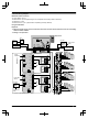
Main monitor
#2
#3
Lobby station
#4
#1