Installation and Operating Instructions Video Intercom System — Lobby station/Distributor Model No. Lobby station (16 call buttons) VL-VM series / VL-VM701 Lobby station (8 call buttons) Distributor (VL-VM701)*1 Thank you for purchasing a Panasonic product. Please follow all instructions in this document and save it for future reference. Carefully read the information found in the section titled "2.1 Important safety information" in particular.
Table of Contents 1. Introduction 1.1 System overview ...........................................3 2. Important Information 2.1 2.2 2.3 2.4 2.5 2.6 2.7 2.8 Important safety information ..........................7 Important safety instructions .........................8 Privacy and rights of portrait .........................8 Disclaimer .....................................................8 Other important information ..........................8 General information ......................................
1. . Introduction 1. Introduction 1.1 System overview This document explains how to install and configure a Video Intercom System for Apartment Complexes comprised of the VL-VM series devices. Additionally, general information is provided for connecting other devices to the system. 1.1.1 Main features Easy installation – A flexible system that accommodates up to 32 rooms can be designed by combining call button modules. – The lobby station supports the two main wiring methods (star and bus).
1. Introduction 1.1.
1. Introduction Bus wiring example Example 2: 32 call buttons on the lobby station/6 lobby stations E B #4 #8 #3 #7 #2 #6 #1 #5 F D D C A G H #1 #2 #3 #4 #5 #6 C System devices R See page 23 for information about connections for power supply units. No.
1. Introduction 1.1.3 Lobby station components The lobby station is composed of the following modules according to the number of rooms. See page 26 for information about assembly. Note: R Regardless of the number of button module combinations, a maximum of 8 button modules can be used in 1 lobby station. Large type lobby station example Module Model no. Number of call buttons (Unit: pcs.
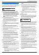
2. . Important Information 2. Important Information 2.1 Important safety information To prevent severe injury or loss of life or property, and to ensure proper and safe operation of your product, read this section carefully before using the product. WARNING Preventing fire, electric shock and short circuits R Leave installation work to the dealer. Installation work requires technical knowledge and experience. Electrical connection work should be performed by certified personnel only.
2. Important Information 2.2 Important safety instructions When using this product, basic safety precautions should always be followed to reduce the risk of fire, electric shock, or personal injury. Use only the power supply unit indicated in this document. SAVE THESE INSTRUCTIONS Graphical symbols for use on equipment and their descriptions Symbol Explanation Alternating current (A.C.) Direct current (D.C.) Protective earth 2.
2. Important Information For business users in the European Union If you wish to discard electrical and electronic equipment, please contact your dealer or supplier for further information. Panasonic Testing Centre Panasonic Marketing Europe GmbH Winsbergring 15, 22525 Hamburg, Germany http://www.ptc.panasonic.eu/doc Information on Disposal in other Countries outside the European Union This symbol (A) is only valid in the European Union.
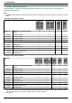
3. . Preparation 3. Preparation VL-VM301 3.1 System devices The following modules or devices are sold separately. Please contact your nearest Panasonic dealer for sales information. Compatible system devices (as of July 2018) Item Quantity 1-button module 1 Flat cable Used to connect modules. 1 2-pin terminal block Used when using star wiring. 1 Spare button Used as a spare when replacing name plates. 1 Name sheet Used as a spare when replacing name plates.
3. Preparation VL-VM302 Item VL-VM303 Quantity Item Quantity 2-button module 1 3-button module 1 Flat cable Used to connect modules. 1 Flat cable Used to connect modules. 1 2-pin terminal block Used when using star wiring. 2 2-pin terminal block Used when using star wiring. 3 Spare button Used as a spare when replacing name plates. 1 Spare button Used as a spare when replacing name plates. 2 Name sheet Used as a spare when replacing name plates.
3. Preparation VL-VM304 Item VL-VM801 Quantity 4-button module 1 Flat cable Used to connect modules. 1 Item Extension cable Used to connect 2 frames of a lobby station together. Quantity 1 VL-VM902 (for France) 2-pin terminal block Used when using star wiring. 4 Spare button Used to prevent the removal of name plates. 2 Name sheet Used as a spare when replacing name plates. 4 Screw (2 mm ´ 3 mm) Used to prevent the removal of name plates.
3. Preparation Item Quantity Side plate Used to secure and attach the left and right sides of modules. 2 Screw (3 mm ´ 5 mm) Used to attach modules to side plates. 10 Upper/lower plate Used to attach the back box to a wall. 2 Screw (4 mm ´ 25 mm) Used to secure the upper and lower plates. Hexalobular screw (3 mm ´ 12 mm) Used to secure the lobby station to the back box. Hexalobular wrench 4 1 1 VL-VM603 (large type) Item Back box Quantity 1 Item Quantity Frame Used to assemble modules.
3. Preparation VL-VM502 (small type) Item VL-VM503 (large type) Quantity Surface mount cover 1 Bracket Used to attach the surface mount cover to the back box. 4 Hex screw (3 mm ´ 5 mm) Used to attach the bracket to the back box. Dustproof sheet Used to attach the sheet to the bottom of the back box. 14 Quantity Surface mount cover 1 Bracket Used to attach the surface mount cover to the back box. 4 Hex screw (3 mm ´ 5 mm) Used to attach the bracket to the back box.
3. Preparation 3.1.2 Distributor 3.1.3 Power supply unit VL-VM701 (bus wiring) VL-PS240 (0.6 A type) Item Quantity Item Quantity Distributor 1 Power supply unit 1 Screw (3.8 mm ´ 20 mm) Used to secure the distributor to the wall. 2 Screw (4 mm ´ 40 mm) Used to secure the power supply unit to the wall. 2 Cable binder Used to secure the connected wires. 2 Cable binder Used to secure the AC and DC wires. 2 VL-PS2410 (2.5 A type) Item Quantity Power supply unit 1 Screw (3.
3. Preparation A Lens cover 3.2 Device diagrams B Light C Speaker 3.2.1 Lobby station D Call buttons Illuminates in dark environments depending on the DIP switch settings (page 40). Front view Example: 12 call buttons on lobby station E Microphone F Unlock indicator ( E A B C ; blue) G Talk indicator ( ; amber) H Call indicator ( ; red) I Blank panel F G H J Flat cable connector Used to connect modules together. K DIP switches See page 40.
3. Preparation 3.2.2 Distributor Example: distributor with the cable cover removed G I A B C J D E F G K L H A Connection terminals (output) for next distributor B Connection terminals (input) for lobby station, extension box or previous distributor C DIP switches for distributor ID setting See page 41. D DC IN connection terminals for power supply Used to connect the distributor to the power supply unit. E POWER indicator See page 43. F ACCESS indicator See page 43.
3. Preparation 3.3 Specifications External material Whole system capacity R Lobby station (VL-VM series): Star wiring: up to 1 Bus wiring: up to 6 Stainless steel (surface mount cover) Aluminum (partially PC and ABS) Talking method Hands-free Image sensor 1/4 inch CMOS sensor (approx. 1M pixels) Viewing angle Horizontally: approx. 170° Vertically: approx. 110° Minimum illuminance required 1 lx (within approx.
3. Preparation Distributor (VL-VM701; sold separately) The distributor is for indoor use only. Power source Power supply unit VL-PS240: 24 V DC, 0.6 A or VL-PS2410: 24 V DC, 2.5 A Power consumption Standby: 1.6 W Operating: 9.0 W Measurement conditions: – Consumption for 1 VL-VM701 device when other VL-VM701 devices are not supplying power. – VL-MV10 (1 pcs.) is connected to VL-VM701. – VL-PS240 is used as the power supply unit.
4. . Installation 4. Installation 4.1 Installation cautions Refer to the information found in 2 Important Information (page 7) before installing the product. CAUTION R Always connect power cables to the appropriate connection terminals. Incorrectly connecting the power cables may damage the power supply unit. R To prevent the power cables from disconnecting and to prevent electric shock, secure the power cables using the included cable binders and attach the cable covers.
4. Installation wire should be connected to, and insert the DC wires as shown. 4.2.1 Connecting the AC wires and DC wires (VL-PS240) 1 Strip the ends of the wires that connect to the power CAUTION supply unit as shown below. AC wires DC wires 45 mm 25 mm 4 7 mm 7 mm 2 Remove the cable cover screws and then remove the R Insert the power cables firmly all the way into the terminals. If the cables are not inserted all the way, heat may be generated.
4. Installation wire should be connected to, and insert the DC wires as shown. 4.2.2 Connecting the AC wires and DC wires (VL-PS2410) 1 Strip the ends of the wires that connect to the power CAUTION supply unit as shown below. AC wires DC wires 45 mm 25 mm 4 7 mm 7 mm 2 Remove the cable cover screws and then remove the cable covers. R Insert the power cables firmly all the way into the terminals. If the cables are not inserted all the way, heat may be generated.
4. Installation 4.2.3 Information about the power supply unit After connecting the power supply units, make connections to each device. Note: R The VL-PS2410 power supply unit has 6 DC OUT connection terminals. (Use the VL-PS2410 so that the combined output does not exceed 2.5 A. Check the power consumption of each device for more information.) R Other than for VL-MV10 bus-powered main monitors, use the power supply units included with the main monitors or connect the power cord of the main monitors.
4. Installation Example: when a VL-MV10 is connected using 2 VL-PS2410 power supply units The system consists of 2 VL-PS2410 power supply units. #4 #8 #3 #7 #2 #6 #1 #5 1 4.2.4 Mounting on a DIN rail Attach the power supply unit to the DIN rail so that the bottom hook is positioned at the bottom of the power supply unit. 1 Hang the top hooks (A) of the power supply unit on the top of the DIN rail. R At this point the power supply unit will be hanging from the DIN rail but will not be secure.
4. Installation 4.3 Installing the lobby station Required items – – Module parts kit (sold separately) with lobby station assembly Back box parts kit (sold separately) Surface mount cover parts kit (sold separately)*1 Extension cable (sold separately) used to connect 2 frames of a lobby station together – Wires that connect the lobby station to the electric lock, and K-IN connection device (example: access controller and/or open door sensor, etc.) See "4.6.2 Wire type and maximum wire length (Page 39)".
4. Installation 4.3.2 Assembling lobby station modules 4.3.3 Connecting flat cables The lobby station is composed of a combination of modules according to the number of rooms connected to. – See page 6 for information on the composition of each module. – See page 10 for information on the items included with each module. Example: lobby station for camera module ´ 1 pcs. + button module ´ 3 pcs. + blank panel ´ 1 pcs.
4. Installation 4.3.4 Connecting 2 frames of a lobby station using the extension cable 1. Remove the waterproof rubber from the panel, and then remove the screws (A) on the left and right side of the module and panel. When connecting 2 frames of a lobby station together, connect them using the VL-VM801 extension cable (sold separately; A) as shown below. Example: lobby station for camera module ´ 1 pcs. + button module ´ 8 pcs. + blank panel ´ 2 pcs. (2 of the included flat cables will not be used) A 2.
4. Installation 4.3.6 Installing the lobby station to a wall The following 2 methods can be used for installing the lobby station. – flush mounting using the back box (sold separately) – surface mounting using the back box and surface mount cover (sold separately) VL-VM602 (small type: back box) Front view Side view Back box dimensions and preparation 206 mm 1. Open a hole in the wall for the back box. R Note the dimensions of the back box.
4. Installation 4.3.7 Flush mounting using the back box Installing 2 frames of a lobby station 1 Open the knockout holes of the back box and pass When connecting 2 frames of a lobby station together, use the extension cable (sold separately) and install to the wall as follows. cables through them. R See the instructions in "Back box dimensions and preparation (Page 28)". 2 Install the back box in the wall. 3 Attach the upper and lower plates (A) using 4 screws A B (B) to the back box.
4. Installation 4.3.8 Surface mounting using the back box and surface mount cover 5 Connect the wires and cables to the lobby station. 1 Open the knockout holes of the back box and pass 6 Attach the lobby station to the back box, and then use cables through them. R See the instructions in "Back box dimensions and preparation (Page 28)". R See "4.6.2 Wire type and maximum wire length (Page 39)". the hexalobular wrench to secure the lobby station to the back box using 1 hexalobular screw (A).
4. Installation 8 After securing the surface mount cover to the back box, caulk the top and side of the surface mount cover with water-resistant sealant. Do not caulk the bottom side. Installing 2 frames of a lobby station When connecting 2 frames of a lobby station together, use the extension cable (sold separately) and install to the wall as follows.
4. Installation 4.3.9 Connecting the wires Camera module Important: R Make sure you turn off the power to all devices at the breaker before performing any wiring work. Failure to observe this may cause product failure. 1 Remove the terminal cover from the camera module. G E F 7 mm 2 Strip the wires from all devices as below.
4. Installation 10 When using bus wiring and VL-VM701 7 When using bus wiring: Insert the wires from the distributor or the extension box into the 6-pin terminal block, tighten the terminal block screws, and then attach the terminal block to the line connection terminals. R Connect the wires as follows. L1 and L2: Distributor or extension box distributor: Make the following connections for the distributor. a. Remove the cable cover screws and then remove the cable covers.
4. Installation Distributor 4.4 Installing the extension box (sold separately) D D D D CBA 7 mm 7 mm A DC wires from power supply unit B Wires from lobby station, extension box, or previous distributor C Wires from next distributor D Wires from main monitor A A A Cable binders connected to cable binder holes Note: R Make sure the wires are inserted fully into the terminal block and that the terminal block screws are tight enough to prevent the wires from pulling out.
4. Installation 4.5 Installing the distributor (sold separately) Required items – – – – Distributor (VL-VM701; sold separately) Cable binders (included with distributor) Screws (included with distributor) Wires for the distributor connection (user supplied) See 4.6.2 Wire type and maximum wire length (Page 39). 4.5.2 Attaching directly to a wall Attach the distributor to the wall securely using the 2 mounting screws (A). R Attach the bottom cable cover after attaching the distributor to the wall.
4. Installation 4.6 Wiring Connections 4.6.1 Wiring schematics Note: R See page 23 for information about connections for power supply units. R See page 40 for information about lobby station DIP switch settings. R See page 41 for information about distributor DIP switches when using bus wiring. R Insert the wires fully into the connection terminals. After inserting the wires, pull slightly on each wire to make sure it is firmly connected.
4. Installation Bus wiring examples Maximum number of devices R Lobby station: up to 6 R Main monitor: up to 32 (depending on the composition of the lobby station’s modules) R Distributor: up to 8 R Extension box: up to 1 (required when expanding the lobby stations) Using the distributor Important: R When using bus wiring, do not connect wires from main monitors to the terminals on the rear of the lobby station's button modules. R Wiring is non-polarised.
4. Installation Using the extension box and distributor Important: R When using bus wiring, do not connect wires from main monitors to the terminals on the rear of the lobby station's button modules. R When connecting to an extension box: – Set all DIP switches of the extension box (VL-V703) to off. – Do not connect wires to connectors 2 to 4 for the V700/VM701 on the extension box (VL-V703). – Cannot monitor from the main monitor.
4. Installation 4.6.
4. Installation 4.7 DIP switch settings 4.7.1 Lobby station DIP switch settings The following lobby station DIP switch settings are required when installing the lobby station.
4. Installation 4.7.2 Distributor DIP switch settings The following DIP switch settings are required when installing the distributor using bus wiring. – Distributor ID settings #1 – #8: applicable DIP switches (A) must be configured at each distributor. – Room number ID settings A – f: applicable DIP switches (B) must be configured according to each button number of the lobby stations and rooms.
4.
4. Installation 4.8 Distributor POWER and ACCESS indicators You can use the POWER and ACCESS indicators to check the status of devices. R All distributors lit in green indicate that there is no problem. R A red flashing indicator indicates that there is an error.
4. Installation 4.10 Room name plates The room name plates of the lobby station can be attached in the follow ways. – Attached so that room name plates can be easily attached and removed in order to change the names of residents. – Attached so that room name plates cannot be easily attached and removed (tamper prevention). After consulting with contractors and facility staff, use screws to secure each name button module to the lobby station. Removing/attaching room name plates 1. 2. 3. 4.
5. . Basic Operations 5. Basic Operations 5.1 System conditions and limitations Please note the following system conditions and limitations. R Only one call or monitoring session can be handled at a time. – If the call button for the same lobby station is pressed multiple times, the last call button pressed has priority. – If the call buttons for multiple lobby stations are pressed, the first call button pressed has priority.
6. . Other information 6. Other information 6.1 Basic troubleshooting For advanced troubleshooting, refer the information on the following web site. https://panasonic.net/cns/pcc/support/intercom/vl-vm If the system does not operate correctly, particularly after installing or modifying the system, first check the following points.
6. Other information 6.2 Cleaning Wipe the product with a soft, dry cloth. R For excessive dirt, wipe the product with a slightly damp cloth. R When the product is installed near ocean coasts, wipe the product with a slightly damp cloth once every 2 to 3 months. Important: R Do not use any cleaning products that contain alcohol, polish powder, powder soap, benzine, thinner, wax, petroleum, or boiling water. Also do not spray the product with insecticide, glass cleaner, or hair spray.
1006, Oaza Kadoma, Kadoma-shi, Osaka 571-8501, Japan http://www.panasonic.