Installation and Operating Instructions Video Intercom System — Lobby Station Model No. VL-VN1900 Thank you for purchasing a Panasonic product. Please follow all instructions in this document and save it for future reference. Carefully read the information found in the section titled "2.1 Important safety information" in particular. This system is an auxiliary system; it is not designed to provide complete protection from property loss.
Table of Contents 1. Introduction 1.1 1.2 1.3 1.4 System overview ...........................................3 Included items ...............................................6 Optional items ...............................................6 About this document .....................................7 2. Important Information 2.1 2.2 2.3 2.4 2.5 2.6 2.7 2.8 2.9 Important safety information ..........................8 Important safety instructions .........................9 Privacy and rights of portrait ....
1. . Introduction 1. Introduction 1.1 System overview This document explains basic information required to install and configure a VL-VN1900 Lobby Station for use with a Video Intercom System that is comprised of the following devices. R VL-MN1000 Room Monitor R VL-VN1900 Lobby Station R VL-VN1500 Door Station R VL-VN1700 Control Box General information about connecting other devices to the system is also provided. 1.1.
1. Introduction 1.1.2 System configuration Basic system example (up to 200 SIP devices*1) C H F M B 1 2 R1 R2 R3 1 2 R1 R2 R3 A I J L K Facility staff office G D Fully expanded system example (up to 2000 SIP devices**1, requires control box) 1 2 R1 R2 R3 1 2 R1 R2 R3 Facility staff office Control box E *1 "SIP devices" include lobby stations, room monitors, door stations, and SIP phones.
1.
1. Introduction Item 1.2 Included items The following items are included in addition to the lobby station. Item Flush mount box Quantity DC plug with ferrite core Used to connect the power supply unit to the lobby station. 1 Quantity 1 Note: R Do not remove the ferrite core. Hex screw (4 mm ´ 25 mm) Used to secure the lobby station to the flush mount box. 4 Hex wrench 1 4-pin terminal block Used to connect wires to the K-IN connection terminals.
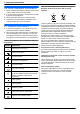
1. Introduction 1.4 About this document Symbols, expressions, and styles The following symbols, expressions, and styles are used in this document. Item How it is expressed Text displayed on the product’s display Text is displayed in a special font, usually enclosed in quotation marks. Example: “IP Config” Buttons with printing on them Button printing is displayed, usually wrapped in thick brackets. Example: M N Procedures Usually written in an abbreviated style. The verb may be omitted.
2. . Important Information 2. Important Information 2.1 Important safety information To prevent severe injury or loss of life or property, and to ensure proper and safe operation of your product, read this section carefully before using the product. WARNING Preventing fire, electric shock, and short circuits R Leave installation work to the dealer. Installation work requires technical knowledge and experience. Electrical connection work should be performed by certified personnel only.
2. Important Information 2.2 Important safety instructions When using this product, basic safety precautions should always be followed to reduce the risk of fire, electric shock, or personal injury. Use only the power supply unit indicated in this document. SAVE THESE INSTRUCTIONS 2.3 Privacy and rights of portrait When installing or using the product, please take into consideration the rights of others with regard to privacy.
2. Important Information 2.6 Other important information R When you leave the product unused for a long period of time, unplug it from the power outlet. R If you stop using this product, remove it from the walls to prevent it from falling off. R When power fails, this product cannot be used. R Panasonic may not be liable for damages due to external factors such as power failures. 2.7 General information R In the event of problems, you should contact your equipment supplier in the first instance.
2. Important Information 2.8 For India only 2.9 For Europe Declaration of Conformity with the requirements of the E-Waste (Management) Rules Declaration of Conformity The Product is in conformity with the requirements of the reduction of hazardous substances of the E-Waste Rules. The content of hazardous substance with the exemption of the applications listed in SCHEDULE II of the E-Waste Rules: 1. Lead (Pb) – not over 0.1% by weight; 2. Cadmium (Cd) – not over 0.01% by weight; 3.
3. . Preparation 3. Preparation Motion sensor 3.1 Device diagrams Turns on the display when a visitor is detected. Keypad Front view H A I B Speaker Camera lens Microphone Search buttons (M N and M N) Used to select items shown on the display. C Cancel button (M Call button (M N) N) D Camera lens adjustment lever E K-OUT connection terminals (output) J F K L Used to send signals to an electric lock. DC IN connector Used to connect the lobby station to the power supply unit.
4. . Installation 4. Installation 4.1 Installation cautions Refer to the information found in 2 Important Information (Page 8) before installing the product. 4.2.1 Connecting the AC wires, DC wires, and DC plug 1 Strip the ends of the wires that connect to the power supply unit as shown below. AC wires CAUTION DC wires 25 mm 45 mm R Always connect power cables to the appropriate connection terminals. Incorrectly connecting the power cables may damage the power supply unit.
4. Installation wire should be connected to, and insert the DC wires as shown. 6 Solder the ends of the DC wires to the DC plug. Use insulation sleeves to insulate the wires. CAUTION C R Insert the power cables firmly all the way into the terminals. If the cables are not inserted all the way, heat may be generated.
4. Installation 4.2.2 Mounting on a DIN rail Attach the power supply unit to the DIN rail so that the bottom hook is positioned at the bottom of the power supply unit. 1 Hang the top hooks of the power supply unit on the top of the DIN rail. R At this point the power supply unit will be hanging from the DIN rail but will not be secure. 2 Pull the lever down, make sure the bottom of the power supply unit is flat against the DIN rail, and then release to lever.
4. Installation 4.3.1 Installation position of the lobby station and camera range Installed on slanted surface, side view Camera height: 1020 mm Surface angle: 60° Camera lens angle: 0° Refer to the following examples and confirm the area viewable by the camera. In each illustration, the viewable area is indicated by "A" and the centre of the camera lens is indicated by "B".
4. Installation 2 Open the knockout holes of the flush mount box, and 4.3.2 Installation 1 Open a hole in the wall for the flush mount box. R Note the dimensions of the flush mount box. then pass all necessary cables and wires (DC plug, LAN cable, wires for electric lock, access controller, open door sensor) through the knockout holes. Front view 353 mm 3 Install the flush mount box in the wall. 4 Attach the vandal proof post to the back of the lobby 159 mm station. R See 4.3.
4. Installation 5 Connect the wires and cables to the lobby station. R See 4.3.3 Connecting the wires and cables (Page 19). 6 Attach the lobby station to the flush mount box, and then use the hex wrench to secure the lobby station to the flush mount box using the 4 screws. R We recommend you view the lobby station’s camera image using a room monitor and adjust the camera lens angle before completing the lobby station installation. See 4.3.4 Adjusting the camera lens angle (Page 20).
4. Installation F 4.3.3 Connecting the wires and cables 1 Connect the LAN cable to the LAN connector. 2 Connect the DC plug to the DC IN connector. R See 4.2 Installing the power supply unit (Page 13) for information about installing the power supply unit. G 3 Strip the wires from the electric lock, access controller, and open door sensor as shown below.
4. Installation 4.3.4 Adjusting the camera lens angle The angle of the camera lens can be adjusted ± 15°. Pushing the lever toward the top of the lobby station points the camera lens down; pushing it toward the bottom points the camera lens up. A A Camera lens adjustment lever 4.3.5 Information about the vandal proof feature When the vandal proof post is installed, the post presses against the vandal proof button and holds the button down as long at the lobby station is installed in the flush mount box.
4. Installation 4.
4. Installation 4.5 Wire and cable specifications Wiring run Lobby station « Switching hub Power supply unit « Lobby station Power supply unit « AC power source Lobby station « Electric lock Access controller Open door sensor Specifications Max. length Cat-5e or higher, stranded, twisted pair, straight 100 m 0.65 mm (22 AWG) approx. 10 m 2 mm (12 AWG) approx. 20 m 1.2 mm (17 AWG) 2 mm (12 AWG) 0.5 mm (24 AWG) 1.
4. Installation 4.6 Connecting other devices 4.6.1 Electric locks You can connect an electric lock to each lobby station via the K-OUT connection terminals. An electric lock is used to open the lobby door in conjunction with another action, such as pressing a button, swiping an access card, inserting a key, entering a door access password, etc. R One electric lock can be connected to each lobby station. R When selecting an electric lock, select a device that meets the following guidelines.
5. . Programming 5. Programming 5.1 Programming overview There are 2 methods used to configure the system. – PC programming: Used to configure the overall system. PC programming involves using a computer and the setup tool (a dedicated program provided by Panasonic) to create configuration files while offline (and typically off-site) that will be uploaded to the system later, when the computer is connected to the same network as the system.
5. Programming 5.2.4 Setup tool main menu The following items are displayed in the main menu of the setup tool. Items may not be available depending on the current project, which items you have finished configuring, etc. 3. Configuration Data Generation Generates configuration files based on the data you have configured using the setup tool. Each device can then download its configuration file when it is first turned on. 4.
5. Programming 5.2.6 Editing a previously saved project 1 2 3 4 5 Start the setup tool. In the left pane, click the desired project. In the right pane, click the desired project data. Click [1. Buildings and rooms configuration]. Follow the on-screen instructions and configure the general system information. 6 After you have configured the items on all of the screens as needed, click [Complete] when prompted. 5.2.7 Generating configuration files 1 2 3 4 Start the setup tool.
5. Programming 5.3 Lobby station management 5.3.1 Issuing access cards Facility staff can use a lobby station for light system management. Authentication is required in order to issue access cards. To authenticate, you can use either the administrator’s access card, or the password used to issue access cards. 1 Press M#N ® enter the administrator password ® M#N. R The default administrator password is "135246".
5. Programming 5.3.2 Switching between room mode and reception mode 1 Press M#N ® enter the administrator password ® M#N. R The default administrator password is "135246". 2 Select “Reception Mode” ® M#N. 3 Select “On/Off Setting” ® M#N. 4 Press M1N or M2N to display the desired setting ® M#N. – “Reception Mode On”: Reception mode is enabled. Visitor calls are directed to a receptionist. – “Reception Mode Off”: Room mode is enabled. Visitor calls can call rooms directly.
5. Programming 5.3.3 List of lobby station management parameters The following parameters are available when using lobby station management. Parameter Description and available settings Default IP Config Allows facility staff to change the IP settings of the lobby station. — Issue Card Allows facility staff to issue access cards for residents. R See 5.3.1 Issuing access cards (Page 27). — Volume Config Allows facility staff to change the speaker volume of the lobby station.
6. . Basic operations 6. Basic operations 6.1 Lobby station operations 6.1.1 Calling a resident 1 Enter the resident’s room number. 2 Press M N to call. Note: R If there are multiple buildings, a building number may need to specified when entering the resident’s room number. See 6.3 Information for visitors (Page 31) for details. 6.1.2 Calling a receptionist 1 Press M 2 Press M 3 Press M N. N or M N to select the desired item. N to call. 6.1.3 Searching the directory 1 Press M N.
6. Basic operations 6.3 Information for visitors We recommend preparing a guide to help visitors. Please refer the following samples.
7. . Other information 7. Other information 7.1 Basic troubleshooting For advanced troubleshooting, refer the information on the following web site. http://panasonic.net/pcc/support/intercom/vn1900 If the system does not operate correctly, particularly after installing or modifying the system, perform the following basic troubleshooting. R Make sure power is being supplied to each device.
7. Other information 7.3 Specifications Lobby Station (VL-VN1900) Power source Power supply unit (VL-PS240): 24 V DC, 0.6 A Power consumption Standby: approx. 3.5 W Operating: approx. 8.5 W Dimensions (mm) (height ´ width ´ depth) Approx. 373´179´6 (excluding sections embedded into the wall) Mass (weight) Approx. 1,500 g Operating environment Ambient temperature: approx. -10 °C to +55 °C Relative humidity (non-condensing): up to 90 % Display Approx. 8.8 cm (3.
7. Other information 7.4 Cleaning Wipe the product with a soft, dry cloth. For excessive dirt, wipe the product with a slightly damp cloth. Important: R Do not use any cleaning products that contain alcohol, polish powder, powder soap, benzine, thinner, wax, petroleum, or boiling water. Also do not spray the product with insecticide, glass cleaner, or hair spray. This may cause a change in colour or quality of the product. 7.
Notes 35
1006, Oaza Kadoma, Kadoma-shi, Osaka 571-8501, Japan http://www.panasonic.