Operating Instructions BL-C1A Network Camera Model No. BL-C20A BL-C1A BL-C20A Indoor Use Only Wired Type Wireless/Wired Type Please read this manual before using, and save this manual for future reference. Panasonic Network Camera Website: http://www.panasonic.
Operating Instructions Main Features [For BL-C20A] Wireless Communication This Network Camera is compatible with a wireless system based on IEEE 802.11b/g. Wireless installation is playing an ever increasing role in flexible communication. The use of encryption ensures security on this kind of network. Communication via Ethernet cable is also available. Digital zoom feature*1 This camera has a 10× digital zoom feature.
Operating Instructions Documentation This manual is for both BL-C1A (Wired Type) and BL-C20A (Wireless/Wired Type). Available features and operations are different in part depending on the model. Read this manual carefully and use the Network Camera properly. (The model no. is indicated on the upper left of the front of the main unit.) The illustrations and images used in this manual are of BL-C20A.
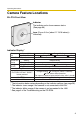
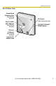
Operating Instructions Camera Feature Locations BL-C1A Front View Indicator The indicator color shows camera status. (See page 96) Lens (Focus: 0.
Operating Instructions BL-C1A Rear View Stand/Tripod Mounting Hole (See Getting Started.) Serial number MAC Address (See Getting Started.) DC IN jack (See Getting Started.) FACTORY DEFAULT RESET Button Ethernet (LAN) port (See Getting Started.
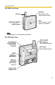
Operating Instructions BL-C20A Front View Antenna FACTORY DEFAULT RESET Button Indicator The indicator color shows camera status. Lens (0.3 m [about 11 13/16 inches]—Unlimited) Note See page 4 for the indicator operations. BL-C20A Rear View Stand/Tripod Mounting Hole (See Getting Started.) Serial number MAC Address (See Getting Started.) DC IN jack (See Getting Started.) Switch (WIRED or WIRELESS) Ethernet (LAN) port (See Getting Started.
Operating Instructions Table of Contents 1 1.1 Camera Monitoring......................................................10 Accessing the Camera ................................................................. 10 1.2 Viewing the Single Camera page................................................. 12 1.2.1 1.2.2 1.2.3 1.2.4 1.2.5 Displaying the Banner ............................................................................. 16 Auto Centering the Image (Click to Center).................................
Operating Instructions 4.3 Buffering or Transferring Images by Motion Detection Signal ...... 70 4.4 Setting the Motion Detection........................................................ 83 4.5 Setting Sensor Log Notification.................................................... 86 5 Using Other Features..................................................89 5.1 Changing Initial Settings on the Single Camera page or the Multi-Camera page ................................................................
Operating Instructions 7.5.2 7.5.3 Setting UPnP™ to Display Camera Shortcut in My Network Places..... 130 Setting the Internet Temporary File Setting on the Web Browser.......... 130 7.6 ASCII Character Table ............................................................... 131 7.7 File Size and Number of Buffered Images ................................. 132 7.8 Specifications............................................................................. 135 Index.......................................
Operating Instructions 1 Camera Monitoring 1.1 Accessing the Camera 1. Start up the web browser on your PC. 2. Enter "http://IP Address (or URL):Port Number" on the address bar, and press [Enter] on the keyboard. • When the port number is 80 (default), you do not need to include the port number in the address. See page 33 for details about the port number. • If the camera image is not displayed, see page 9 and page 10 of the Troubleshooting on the CD-ROM. E.g. http://192.168.0.253:50000 http:// .
Operating Instructions 4. Click the following tabs to display each page. A B C D E F G Select a language. Version Number A To Single Camera page (page 12) C To Buffered Image page (page 22) E To Maintenance page (page 97) G To log in to the camera (page 56) B To Multi-Camera page (page 20) D To Setup page (page 28) F To Support page (page 106) Note When users other than an administrator are accessing the camera, the [Setup] and [Maintenance] tabs are not displayed.
Operating Instructions 1.2 Viewing the Single Camera page 1. Access the camera (see page 10). • The Top page is displayed. 2. Click the [Single] tab at the top of the page. • • When the Security Warning window is displayed, click [Yes] (see page 14). See page 15 for the Security Warning window when using Microsoft® Windows® XP Service Pack 2.
Operating Instructions • • • • • When the camera transmits a dark scene, the camera image may become white, or horizontal lines may be displayed on the screen. This is one of the characteristics of a CMOS sensor. This is not a malfunction. To display the Single Camera page directly, add it to the [Favorites] on the web browser. To view dark images, select [Enable] (default) at Color Night View on the Camera Setup page.
Operating Instructions Security Warning window When trying to view a video (Motion JPEG) for the first time, a Security Warning for ActiveX Controls will be displayed. When using Windows 2000 or Windows XP, log in as an administrator to install ActiveX Controls and enable video (Motion JPEG) viewing. If you cannot install ActiveX Controls or you cannot see the video (Motion JPEG) using Internet Explorer • In Internet Explorer, click [Tools]→[Internet Options]→[Security] tab and click [Custom level].
Operating Instructions Security Warning window on Microsoft Windows XP Service Pack 2 To view a video (Motion JPEG), ActiveX Controls must be installed. Follow the steps shown below to install ActiveX Controls. 1. Click the warning displayed above the tabs, and click [Install ActiveX Control...]. 2. Click [Install].
Operating Instructions 1.2.1 Displaying the Banner An image and its linked website can be specified for a banner. To display the banner, the Banner Display settings need to be set on the Image Display page (see page 89). Clicking the banner displays the website of the set URL Link. The Banner Display is not enabled as the default. 1.2.2 Auto Centering the Image (Click to Center) Using your mouse, click any portion of the camera image when using the digital zoom.
Operating Instructions 1.2.3 Zooming In and Out This Camera has 10× digital zoom feature that uses ActiveX Controls. The digital zoom feature can be used while playing video (Motion JPEG) on the Single Camera, Multi-Camera and Buffered Image pages. The digital zoom feature can be operated by rotating the mouse wheel or clicking the right mouse button. Note • • • • The Click to Center feature is available while zooming in or out. Images can only be moved within the page when magnification is ×1.
Operating Instructions 1.2.4 Capturing a Still Image Still images can be saved on your PC. 1. Select an image resolution to display an image. 2. Click the Capture image button. Capture Image Button • The camera image opens in another window. 3. Right-click the image, and select [Save Picture As...]. • The Save as dialog box is displayed. 4. Specify a folder, enter the file name and click [Save]. • The camera image is saved in the folder. 5. Click [Close].
Operating Instructions 1.2.5 Using the Operation Bar Brightness: Adjusts image brightness in nine steps including [STD] (Standard). Clicking [-] or [+] darkens or brightens the image respectively. Refresh Interval: Sets a refresh interval. (Motion—60-second interval) Resolution: Selects [640 × 480] or [320 × 240] (default) pixels. Image Quality: Selects the image quality. • [Favor Clarity] optimizes the image for good clarity. • [Standard] keeps the standard quality.
Operating Instructions 1.3 Viewing the Multi-Camera page To view multiple cameras on the Multi-Camera page, you need to configure each camera on the Multi-Camera Setup page (see page 92). 1. Access the camera (see page 10). • The Top page is displayed. 2. Click the [Multi] tab at the top of the page. • The Multi-Camera page can display up to 12 camera images. Capture Image Button (See page 18) Switches displayed cameras. If you select [All] at the View Type, video (Motion JPEG) cannot be displayed.
Operating Instructions Note • • • • • • • • • The digital zoom feature and the Click to Center feature can be used for video (Motion JPEG) only. When selecting [All] for the View Type, all images are displayed in 160 × 120 pixels resolution. 640 × 480-pixel images cannot be displayed on the Multi-Camera page. When viewing video (Motion JPEG), we recommend using an Ethernet switching hub instead of a repeater hub to prevent degradation in video display.
Operating Instructions 1.4 Viewing the Buffered Image page To buffer images in the camera's internal memory, you need to set up the image transfer settings (see page 60 or page 70). Buffered images can be viewed on this Buffered Image page. 1. Access the camera (see page 10). • The Top page is displayed. 2. Click the [Buffered Image] tab at the top of the page. 3. Click the trigger number. The trigger number is displayed (see page 60 or page 70). The trigger is displayed (see page 60 or page 70).
Operating Instructions 4. Display images by clicking buttons below. The date and time when the images were buffered are displayed. Month (Sep), day (20), hour (02), minute (58), second (15), millisecond (120), AM/PM (PM), the number and the total number of frames (1/10) are displayed. [Play]: The buffered images are displayed in sequence. []: The previous or next image is displayed. [<100], [<10] or [10>], [100>]: The 10th or 100th image before or after the current image appears.
Operating Instructions 1.4.1 Deleting Buffered Images If you intend to delete images for each transfer method, click [Delete Buffered Images] on the Trigger page (see page 60 or page 70). Note • If you are buffering images to the internal memory, the following operations also delete all buffered images. – Turning off the camera. – Saving the Date and Time page. – Restarting, updating firmware or resetting the camera to factory default.
Operating Instructions 1.5 Viewing Still Images on Your Cell Phone Still images can be viewed over the Internet from a compatible cell phone. Enter "http://IP address (or URL):Port Number/mobile" on a cell phone and press [OK]. • When the port number is set to 80 (default), it is not required. E.g. http:// . (or • • • . . :50000/mobile .viewnetcam.com:50000/mobile) Allow access from the Internet to access the camera from cell phones.
Operating Instructions Note • If the image is not displayed properly, try the following 2 URLs. 1. http:// IP address(or URL):Port Number/MobileH for HTML. (or .viewnetcam.com:50000/MobileH) 2. http:// IP address(or URL):Port Number/MobileX for XHTML. (or • • • • .viewnetcam.com:50000/MobileX) Some cell phones are not compatible with Panasonic Network Cameras. Some phones may allow viewing only on port 80, and some may not support password authentication.
Operating Instructions 1.5.1 Enabling or Disabling the Buffer/Transfer on Your Cell Phone 1. Access camera images from your cell phone, and log in as an administrator (see page 25). 2. Select [Buffer/Transfer]. 3. Select a trigger number that you want to enable or disable. Example: Enabling the Buffer/Transfer setting (No.1). • Selecting [Control Page] changes to the previous page. 4. Select [Save].
Operating Instructions 2 Using the Camera's Basic Features 2.1 Setup Page of the Camera 1. Access the camera (see page 10). • The Top page is displayed. Note • • When [Permit access from guest users] is set on the Security: Administrator page, click the [Login] tab (see page 56) and log in as an administrator. When users other than an administrator are accessing the camera, the [Setup] and [Maintenance] tabs are not displayed. 2. Click the [Setup] tab at the top of the page.
Operating Instructions Basic (1) Network Configures network settings to connect the camera to the network (see page 31). (2) [For BL-C20A] Wireless Configure a wireless network (see page 36). (3) UPnP Enables automatic port forwarding and creates a shortcut to the camera (see page 39). (4) DynamicDNS Registers with the DynamicDNS service (see page 42). (5) Date and Time Sets the date and time, automatic time adjustment and daylight saving time settings (see page 48).
Operating Instructions Advanced (12) Image Display Sets the resolution, image quality and refresh interval of the Single Camera and Multi-Camera page, Limit Continuous Motion JPEG setting*1, language and banner display (see page 89). (13) Multi-Camera*1 Sets the camera IP address or host name, and camera name on the Multi-Camera page (maximum 12 cameras) (see page 92). (14) Operation Time Sets the time period to display camera images (see page 94).
Operating Instructions 2.2 Connecting the Camera to Your Network The Network page offers three options to configure the camera. • [Automatic Setup] automatically assigns an unused IP address to the camera, and uses UPnPTM (Universal Plug and Play) to configure your router. • [Static] allows the user to use a specific IP address. • [DHCP] is offered for ISPs that require this option. 1. Click [Network] on the Setup page. 2. Click a connection mode. Most common mode of setup. Uses a static IP address.
Operating Instructions DHCP Setup • Static Setup Clicking [Cancel] takes you back to the previous page without saving changes. 4. Click [Save] when finished. • • The new settings are saved. When finished, the following page is displayed. Note The current network settings are shown on the Status page in the Maintenance section (see page 98). 5. Click [Restart]. • • • The camera restarts, and the Top page is displayed.
Operating Instructions Note If you do not know the camera IP address when setting [Automatic Setup] or [DHCP Setup], it can be searched for by using the Setup Program (see page 120). Setting Allow Access from the Internet (Automatic Setup Only) Description • The Allow Access from the Internet setting automatically configures the router's Port Forwarding setting (some routers call it "Address Translation", "Static IP Masquerade", "Virtual Server" or "Port Mapping").
Operating Instructions Setting Host Name (DHCP Only) Description • • If your ISP uses the DHCP function, which automatically assigns an IP address to the camera, enter the ISPassigned host name. (The host name may be used as an authentication.) Enter ASCII characters for the host name (see page 131). Note that [Space], ["], ['], [&], [<] and [>] are not available.
Operating Instructions Setting Connection Type *1 Description • Select [Auto Negotiation] normally. For wireless connection (BL-C20A only), [Auto Negotiation] must be selected. If the camera cannot be accessed, see page 9 of Troubleshooting on the CD-ROM. If the IP address is automatically obtained from a DHCP server, this field does not need to be set.
Operating Instructions 2.3 [For BL-C20A] Using Wireless LAN Wireless communication is possible by adjusting the settings of the wireless LAN to those of the wireless router. Take a note of the settings and save them for reference. For more information about wireless settings, please refer to http:// panasonic.co.jp/pcc/products/en/netwkcam/. 1. Click [Wireless] on the Setup page. 2. Set each parameter for Wireless Configuration.
Operating Instructions 3. Set each parameter for Encryption. Setting Description Cipher • • Select to encrypt or not encrypt. To prevent unauthorized users from reading data, selecting [WEP] is recommended. WEPKey Selection • The checked WEPKey is used as the standard WEPKey. Check the same WEPKey as the one selected for the router.
Operating Instructions Note • • Some wireless devices do not support the WEP 152 bit encryption. The camera supports only open system authentication. If the wireless router or access point is set to shared key authentication, set it to auto or open system. 4. Click [Save] when finished. • • The new settings are saved. When finished, "Success!" is displayed. 5. Click [Go to Wireless configuration page]. • The Wireless page is displayed. 6. Set the switch to WIRELESS.
Operating Instructions 2.4 Using UPnP™ (Universal Plug and Play) UPnPTM can automatically configure your router to make it accessible from the Internet. In order to use this feature, your router needs to support UPnPTM, and it must be enabled. UPnPTM is disabled on most routers by default. See http:// panasonic.co.jp/pcc/products/en/netwkcam/ and your router's manual for details of how to enable UPnPTM. After UPnPTM is enabled on the router, set [Enable] for auto port forwarding. 1.
Operating Instructions 3. Click [Save] when finished. • • The new settings are saved. When finished, "Success!" is displayed. 4. Click [Go to UPnP page]. • 2.4.1 The UPnP page is displayed. Connecting the Camera to a Router that Supports UPnP™ To allow access from the Internet with a router supporting UPnPTM, follow the procedures shown in Getting Started. Note • • On some routers, the UPnPTM feature is disabled by default.
Operating Instructions 2.4.2 Connecting the Camera to a Router that does not Support UPnP™ To allow access from the Internet with a router that does not support UPnPTM, follow the procedures below. 1. Select [Static] on the Network page. (1) Access the camera (see page 10). (2) Click the [Setup] tab at the top of the page. (3) Select [Static] on the Network page. • The Static IP Address Configuration page is displayed.
Operating Instructions 2.5 Registering with the DynamicDNS service DynamicDNS is a service that allows you to assign an easy-to-remember name to the camera, for example, similar to your favorite web site. It also allows you to easily access the camera, even when your ISP changes the IP address. Panasonic Communications recommends that you register with a DynamicDNS to access the camera from the Internet. See http://www.viewnetcam.com for details about the Viewnetcam.com service. 1.
Operating Instructions 3. Click [Save]. • Clicking [Cancel] cancels your settings without saving changes, and the DynamicDNS window is displayed. Setting Description Personal (Camera) URL • The camera's personal URL will be displayed after you register with the Viewnetcam.com service. Your Account Link • The URL required to register with the Viewnetcam.com service is displayed. Clicking [Your Account Link] item name displays the Viewnetcam.com registration website. 4. Click [OK].
Operating Instructions 8. Access your camera with the registered URL from the Internet (see page 10). • When the Top page is displayed, Viewnetcam.com registration is complete. Note • • It may take a maximum of 30 minutes for the registered URL to work. If "Expired" is displayed for the Personal (Camera) URL on the Viewnetcam.com page or for the Camera URL at Viewnetcam.com on the Status page, restart the camera. After that, confirm that your registered URL is displayed on the pages.
Operating Instructions 3. Set each parameter. • • Clicking [Cancel] cancels your settings without saving changes. DynamicDNS information can be obtained from companies in the DynamicDNS service industry. Setting Description DynamicDNS Server URL*1 Input URL acquired from the DynamicDNS service industry company. Enter 1—255 characters. The URL must be started with "http://". Updating time Specify the updating time. User Name*2 Input User Name acquired from the DynamicDNS service industry company.
Operating Instructions Note • It may take several minutes for the registered URL to connect. • Some DynamicDNS services may not connect. Confirming Internet access Due to the router's specifications, the image may not be displayed even if you access the camera from your PC on the same LAN as the camera. In this case, try: • Accessing from a PC on another network (see page 10) • Accessing from your cell phone (see page 25) 2.5.
Operating Instructions How the DynamicDNS service works DynamicDNS service server DNS server 3. New address registered with 2. Camera reports new address DNS server On-site Network Camera ISP 4. DNS looks up Internet current address 1. Global IP address changes Off-site PC 5. Camera connection established 1. Your ISP assigns a global IP address to your Internet access account that changes periodically. This is the address needed to access the camera over the Internet. 2.
Operating Instructions 2.6 Setting the Date and Time The Date and Time page allows you to set and confirm the date and time. The date and time are used for the settings of the trigger setting, sensor log, operation time and Buffered Image page. Note Saving a new date and time deletes all buffered images on the internal memory. 1. Click [Date and Time] on the Setup page. 2. Set each parameter. • Set [Automatic Time Adjustment] to synchronize the time automatically with an NTP server.
Operating Instructions Setting Time Setting Description • Set the date and format (AM/PM or 24 H). The interface and available values depend on the format. The date and time are used for the settings of the trigger setting, sensor log, operation time and Buffered Image page. Note that the format for the subject and file name of Emails by E-mail or FTP transfer can only be 24 h.
Operating Instructions 2.7 Changing Camera Settings The Camera page allows you to set the camera name, white balance, AC power source frequency and color night view. 1. Click [Camera] on the Setup page. 2. Set each parameter. • Clicking [Cancel] cancels your settings without saving changes. Setting Camera Name Description • • The camera name is displayed on the Single Camera page.
Operating Instructions Setting White Balance Description Select from the following options. • Auto (default) — Automatic adjustment • Fixed Indoor — Electric bulb (2800 K) • Fixed Fluorescent (White) — White (3600 K) • Fixed Fluorescent (Daylight) — Daylight (4000 K) • Fixed Outdoor — Solar light (6000 K) Note The kelvin (symbol: K) is the standard unit for color temperature. AC Power Source Frequency • This setting may correct flickering caused by power line frequency.
Operating Instructions 3 Registering Users 3.1 Changing the Authentication Setting and Administrator User Name and Password The Security: Administrator page allows you to change authentication, and the administrator's user name and password. An authentication window allows registered users to access the camera. Note • If you access the camera for the first time, the window for setting the administrator's user name and password is displayed.
Operating Instructions 2. Set each parameter. • Clicking [Cancel] cancels your settings without saving changes. Setting General Authentication Description Authentication has 3 phases. • If you set [Permit access from guest users], the camera does not display the authentication window in camera access. All guest users can view images without a user name and password. Note If you set [Permit access from guest users], [Login] tab is displayed at the top of the page.
Operating Instructions Setting User Name/ Password Description • • User Name (6 to 15 characters): Enter the user name. Password (6 to 15 characters): Enter the password. Note • • The password must be different from the user name. Retype Password: Reenter the password. Enter ASCII characters (see page 131). Note that [Space], ["], ['], [&], [<], [>] and [:] are not available. Note • • • When setting authentication, set the user name and password, and save them.
Operating Instructions Administrator/General Users/Guest Users The camera has 3 user levels (administrator, general users and guest users). Items Administrator General Users Guest Users User Name and Password Required Required Not Required Number of Users 1 50 — Accessible Pages All Pages Access Level All Operations Pages Except For Pages Except For Setup and Setup and Maintenance page Maintenance page Access level can be set for each general user (see page 57).
Operating Instructions 3.2 Logging in to the Camera If you set [Permit access from guest users] on the Security: Administrator page, [Login] tab is displayed at the top of the page. After you log in as an administrator, the Setup page and the Maintenance page can be accessed. 1. Click [Login] tab at the top of the page. 2. Check a login mode, and click [Login]. Note The authentication window is displayed. Enter the user name and password set for General Users or Administrator. 3.
Operating Instructions 3.3 Creating, Modifying or Deleting General Users The General User page allows you to create, modify or delete general users. Up to 50 general users can be registered. The access level is set for each general user. If you set [Permit access from guest users] or [Permit access from guest users (mobile only)] on the Security: Administrator page, the access level can be set for guest users. Note For general users, the Setup and Maintenance tabs are not displayed. 1.
Operating Instructions 3. Set each parameter. • Settings for general users • Clicking [Cancel] takes you back to the previous page without saving changes. Setting • Settings for guest users Description User ID List • • Up to 50 general users can be registered. The list is used to modify or delete general user settings. User Name/ Password • • User Name (6 to 15 characters): Enter the user name. Password (6 to 15 characters): Enter the password.
Operating Instructions 4 Buffering or Transferring Images 4.1 Procedures of Buffering or Transferring Images The procedures from this page to page 70 are described about settings of the image buffer or transfer. See the procedures below to understand the general outline of the settings.
Operating Instructions 4.2 Buffering or Transferring Images by Timer The Trigger page allows you to enable image buffer/transfer by E-mail or FTP. 1. Click [Trigger] on the Setup page. 2. Click a No. to enable buffer/transfer. 3. Check [Enable Image Buffer/Transfer], and select [Timer] for the trigger, and click [Next>]. Note • • • Click [Delete Buffered Images] to delete images already buffered. Click [Save] to save the settings. The buffered images will be deleted.
Operating Instructions Setting Trigger Description • • Selecting [Timer] enables the camera to buffer/transfer images during the specified date and time by timer. Selecting [Motion Detection] enables the camera to buffer/ transfer images when the motion is detected during the specified date and time. 4. Set the time, and click [Next>]. Note The timer works by an internal clock. Set the date and time before using timer buffer/transfer (see page 48).
Operating Instructions Setting Description Image Resolution • Select an image resolution (640 × 480, 320 × 240 (default) or 160 × 120 pixels) for the buffer/transfer. Image Quality • Select the image quality. [Favor Clarity] optimizes for good quality. [Standard] offers standard quality. (default) [Favor Motion] optimizes for enhanced motion. [Mobile Phone] is for a transfer to a cell phone. Note 640 × 480 pixels cannot be set for a transfer to a cell phone. 6.
Operating Instructions 7. Select the transfer method, and click [Next>]. • • Clicking [
Operating Instructions When you set [FTP] for Transfer Method Select [FTP], and click [Next>]. The following page is displayed. • • Clicking [
Operating Instructions Setting Description Server IP • Address or Host Name*1 If you set a server IP address, set 4 numbers (0—255) and 3 periods, such as "192.168.0.253". Note that "0.0.0.0" and "255.255.255.255" are not available. Or set a host name (1— 255 characters). Port No. • Enter a number (1—65535). Usually set to 21. Login ID*2 • If your ISP requires a login ID, set it (0—63 characters). Password*2 • If your ISP requires a password, set it (0—63 characters).
Operating Instructions When you set [E-mail] for Transfer Method Select [E-mail], and click [Next>]. The following page is displayed. • • Clicking [
Operating Instructions Setting Description SMTP Server IP • Address or Host Name*1 If you set a server IP address, set 4 numbers (0—255) and 3 periods, such as "192.168.0.253". Note that "0.0.0.0" and "255.255.255.255" are not available. Or set a host name (1—255 characters). Port No. • Enter a number (1—65535). Usually set to 25. Reply E-mail Address*2 • Set the sender's E-mail address. We recommend you to set the administrator's E-mail address.
Operating Instructions Setting How to authenticate *1 *2 Description You can select the authentication method: [No authentication], [POP before SMTP authentication] and [SMTP authentication]. POP server authentication may be required by your ISP. In that case, set POP before SMTP authentication. • No authentication: No authentication when sending an email. • POP before SMTP authentication: Some SMTP servers that send e-mails do not have an authentication feature.
Operating Instructions 8. Confirm the settings, and click [Save]. • • The new settings are saved. When finished, "Success!" is displayed. 9. Click [Go to Trigger page]. • The Trigger page is displayed. Note • If you are buffering images to the internal memory, the following operations also delete all buffered images. – Turning off the camera. – Saving the Date and Time page. – Restarting, updating firmware or resetting the camera to factory default.
Operating Instructions 4.3 Buffering or Transferring Images by Motion Detection Signal The Trigger page allows you to enable image buffer/transfer by E-mail or FTP. Note • • • • • The level of motion detection depends on resolution, image quality, and the object being viewed. Check the level by performing motion detection recording. (See page 83) Enabling Motion Detection delays the frame rate of the camera. A change to light or wind conditions may detect motions accidentally.
Operating Instructions Note • • • Click [Delete Buffered Images] to delete images already buffered. Click [Save] to save the settings. The buffered images will be deleted. Clicking [Cancel] takes you back to the Trigger page without saving changes. Setting Description Enable Image Buffer/Transfer • Check the box to enable the Trigger setting. Uncheck the box to disable it. Trigger • Selecting [Timer] enables the camera to buffer/transfer images during the specified date and time by timer.
Operating Instructions 5. Set the image settings, and click [Next>]. • • Clicking [
Operating Instructions 6. Set the image buffer frequency and the Motion deactivation time, and click [Next>]. Note Due to the network environment, object and the number of simultaneous accesses, the camera may not record the number of images that you set. In this case, set the image buffer frequency longer. • Clicking [
Operating Instructions Setting Motion deactivation time Description • • Set the length of time during which the Motion Detection cannot be triggered after saving images temporarily or transmitting them. This function is recommended to prevent sending too many E-mails to a cell phone. After detecting motions, the camera does not detect motions during motion deactivation time, so some images may not be captured. Note The internal memory cannot buffer images during motion deactivation time.
Operating Instructions 7. Select the transfer method, and click [Next>]. • • Clicking [
Operating Instructions When you set [FTP] for Transfer Method Select [FTP], and click [Next>]. The following page is displayed. • • Clicking [
Operating Instructions Setting Description Server IP • Address or Host Name*1 If you set a server IP address, set 4 numbers (0—255) and 3 periods, such as "192.168.0.253". Note that "0.0.0.0" and "255.255.255.255" are not available. Or set a host name (1— 255 characters). Port No. • Enter a number (1—65535). Usually set to 21. Login ID*2 • If your ISP requires a login ID, set it (0—63 characters). Password*2 • If your ISP requires a password, set it (0—63 characters).
Operating Instructions When you set [E-mail] for Transfer Method Select [E-mail], and click [Next>]. The following page is displayed. • • Clicking [
Operating Instructions Note • The camera works only with an SMTP (Simple Mail Transfer Protocol) server. It does not work with mail servers like "Hotmail" that use a web browser. The subject name by E-mail transfer uses only 24 h format. The file name is "image.jpg". E.g. "image:20050101093020500". The underlined numbers mean "9h30min20s500ms on January 1, 2005". The letter "s" is inserted after the day when referring to a daylight saving time zone.
Operating Instructions Setting How to authenticate *1 *2 Description You can select the authentication method: [No authentication], [POP before SMTP authentication] and [SMTP authentication]. POP server authentication may be required by your ISP. In that case, set POP before SMTP authentication. • No authentication: No authentication when sending an email. • POP before SMTP authentication: Some SMTP servers that send e-mails do not have an authentication feature.
Operating Instructions 8. After you confirm the settings and click [Next>], set E-mail notification and click [Next>]. • If you select [Enable], the E-mail Notification When Triggered page is displayed. Enter the settings referring to page 78 — page 80. Setting Description Disable • The camera does not send an E-mail notification when buffering or transferring images. Enable • The camera sends an E-mail notification (up to 3 destinations) when buffering or transferring images. 9.
Operating Instructions 10. Click [Go to Trigger page]. • The Trigger page is displayed. Note • If you set a short interval when transferring to a cell phone, many E-mails will be sent, which may lead to a large phone bill. Therefore, we recommend you to set a long interval. 1 image per minute frequency is recommended. • Motion Detection transfer stops operating until after the camera finishes all transfers.
Operating Instructions 4.4 Setting the Motion Detection The Motion Detection page allows you to adjust the sensitivity of Motion Detection. Threshold: If the threshold is set low, this function detects nearly all movements. Sensitivity: If you set sensitivity high, the amplitude of the motion detection bar gets jumpy. 1. Click [Motion Detection] on the Setup page. 2. Click the Motion Detection bar in Threshold to set the threshold level. 3.
Operating Instructions Threshold Note No responsibility will be taken by our company with respect to consequences resulting from the use of the Motion Detection feature. The Motion Detection feature is not suitable and not recommended for uses that require a high reliability constantly such as surveillance, etc. What is the threshold? The threshold is the minimum value for the camera to detect motions on the image during the motion detection buffering.
Operating Instructions What is the sensitivity? The sensitivity is the level of brightness detected as motion by the camera. A high sensitivity setting enables the camera to detect slight brightness changes. Lower the sensitivity to make the camera detect only big brightness changes. Threshold setting is displayed. The detection level exceeds the threshold when motions are detected.
Operating Instructions 4.5 Setting Sensor Log Notification A sensor log sent once a day at a specified time can be checked. To enable Sensor Log, set Motion Detection for Trigger Setting and check [Enable]. 1. Click [Sensor Log] on the Setup page. When enabling the image/buffer transfer setting and selecting Motion Detection in the Trigger page, the Sensor log window is displayed. 2. Set each parameter. Note • • • Click [Save] to save the settings.
Operating Instructions Setting Description A setup of operation • Sensor log operation can be set here. Time • Set the day of the week and time to send sensor logs via E-mail. SMTP Server IP • Address or Host Name*1 If you set a server IP address, set 4 numbers (0—255) and 3 periods, such as "192.168.0.253". Note that "0.0.0.0" and "255.255.255.255" are not available. Or set a host name (1—255 characters). Port No. • Enter a number (1—65535). Usually set to 25.
Operating Instructions Setting How to authenticate *1 *2 Description You can select the authentication method: [No authentication], [POP before SMTP authentication] and [SMTP authentication]. POP server authentication may be required by your ISP. In that case, set POP before SMTP authentication. • No authentication: No authentication when sending an email. • POP before SMTP authentication: Some SMTP servers that send e-mails do not have an authentication feature.
Operating Instructions 5 Using Other Features 5.1 Changing Initial Settings on the Single Camera page or the Multi-Camera page The Image Display page allows you to change the initial settings (display settings when a user accesses the camera) for the Single Camera, Multi-Camera, Limit Continuous Motion JPEG, Language and Banner Display. 1. Click [Image Display] on the Setup page. 2. Set each parameter. • Clicking [Cancel] cancels your settings without saving changes.
Operating Instructions Setting Description Image Resolution • Select the image resolution. 640 × 480 pixels (Only for the Single Camera page) 320 × 240 pixels (default) 160 × 120 pixels (Only for the Multi-Camera page) Image Quality • Select the image quality. [Favor Clarity] optimizes for good quality. [Standard] offers standard quality. (default) [Favor Motion] optimizes for enhanced motion. Refresh Interval • Select a refresh interval.
Operating Instructions Setting Banner Display Description When checked to [Enable], the setting will be enabled. When unchecked, the setting will be disabled. Note • • • Banner user • When the Banner Display is enabled, the camera accesses the Image URL every time the Single Camera page is displayed. The intermittent and continuous switching of the Single page burdens the PC that stores the image linked with the URL.
Operating Instructions 5.2 Configuring Multiple Cameras The Multi-Camera Setup page allows you to configure camera IP addresses and camera names to view multiple images on the Multi-Camera page. These configurations are required to use the Multi-Camera page. Up to 12 cameras can be configured. The Selfcamera is registered at No. 1 by default. 1. Click [Multi-Camera] on the Setup page. 2. Click Add. Note • • If you click the camera number, the modification page is displayed.
Operating Instructions Setting Display Description • Check this box to enable the camera. IP Address or Host Name*2 • Set an IP address or host name to enable the camera. Port No. • Set a port number (1—65535). *1 Camera Name*3 • *1 *2 *3 This camera name is displayed only on the Multi-Camera page. Set 4 numbers (0—255) and 3 periods, such as "192.168.0.253". Note that "0.0.0.0" and "255.255.255.255" are not available. Enter ASCII characters for the host name (see page 131).
Operating Instructions 5.3 Specifying Operation Time The Operation Time page allows you to limit the time that the camera is in use. The camera image turns to a gray screen outside operation time. Note • • Your privacy may be compromised if the time period is set incorrectly. Confirm the time period after the setup. If you access the camera as an administrator, you can view the image outside the time period. 1. Click [Operation Time] on the Setup page. 2. Click a No. to set the operation time.
Operating Instructions Setting Enable Description • Check the box to enable the setting. Uncheck the box to disable it. Day of the week • Check the box to enable the day. Uncheck the box to disable it. Operation Time To set an operation time, check the time option and set a time period. Check the [Always] option if you are not specifying a time period. • 4. Click [Save] when finished. • • The new settings are saved. The Operation Time page is displayed.
Operating Instructions 5.4 Changing the Indicator Display The Indicator Control page allows you to select an operation for the indicator. There are three options. • Turn indicator on when camera is on. • Turn indicator on during camera access. • Never turn indicator on. 1. Click [Indicator Control] on the Setup page. 2. Select an option. Setting Description Turn indicator • on when camera is on. The indicator always turns on or blinks. See page 3 and page 4 of Troubleshooting on the CD-ROM.
Operating Instructions 6 6.1 Camera Maintenance Maintenance page (1) (2) (3) (4) (5) (6) (7) (8) (9) Maintenance (1) Status Displays the camera settings and status (see page 98). (2) [For BL-C20A] Wireless Status Displays wireless information (see page 98). (3) Session Status Displays information on access to the camera (see page 98). (4) Sensor Log Displays sensor logs (see page 99). (5) Restart Restarts the camera (see page 99).
Operating Instructions 6.1.1 Confirming the Status The Status page allows you to check the status of the camera. The status information provides support for troubleshooting. Clicking [Status] displays the following page. Note See the Panasonic Network Camera support website at http:// panasonic.co.jp/pcc/products/en/netwkcam/ for details about status information. 6.1.2 [For BL-C20A] Confirming the Wireless Status The Wireless Status page allows you to check the status of the wireless connection.
Operating Instructions 6.1.4 Confirming Sensor Logs Displays up to 50 Sensor Logs in chronological order. Old logs will be overwritten by new ones. 1. Click [Sensor Log] on the Maintenance page. 2. Sensor Logs are displayed. Note If the camera is restarted, all sensor logs are deleted. Item Description New Sensor Logs • Displays the number of new sensor logs. Date • Displays the date and time when the Motion Detection is activated.
Operating Instructions 6.1.6 Updating the Camera Firmware The Update Firmware page allows you to update the camera's firmware. If new firmware is available, install it into the camera. Note • • • Do not turn off the power during a firmware update. All buffered images and sensor logs on the internal memory will be deleted after the firmware update. The firmware version is displayed on the Top page and the Status page. 1.
Operating Instructions • The Update page is displayed after about 1 minute for BL-C1A or 90 seconds for BL-C20A. The firmware update process takes about 6 minutes for BL-C1A or 7 minutes for BL-C20A. 4. Click [Browse...]. • A dialog box is displayed to select the firmware. 5. Select the firmware (including directory information) and click [Open]. • The firmware file name is displayed. 6. Confirm the firmware file name, and click [Update Firmware].
Operating Instructions 7. Confirm that the version number on the Top page is updated. Updated version • If the version number is updated, the firmware update is complete.
Operating Instructions 6.1.7 Creating a Configuration File A configuration file can be saved on your PC. You can load camera settings from the configuration file on the Load Settings page (see page 104). Note The saved image has contains private information. It is important to prevent leaks of private information. 1. Click [Save Settings] on the Maintenance page. 2. Click [Save]. 3. Click [Save] on the File Download dialog box. 4. Specify the location, and click [Save] on the Save As dialog box.
Operating Instructions 6.1.8 Loading Settings from a Configuration File Camera settings can be loaded from a configuration file. If you reset the camera to factory default, the camera can load previously used settings from a configuration file. Note • • The configuration file also saves network settings. When settings are loaded, the network settings are also loaded. If you try to update the camera, create a configuration file after updating the firmware.
Operating Instructions 6.1.9 Resetting the Camera to Factory Default All camera settings are reset to factory default when the Execute button is clicked. To restore the wireless connection, access the camera by using a wired connection and set up the wireless configuration. (For BL-C20A, see Getting Started.) 1. Click [Reset to Factory Default] on the Maintenance page. 2. Click [Execute]. • • • The indicator blinks orange, and then turns off for 5 seconds.
Operating Instructions 6.2 Support page (1) (2) (3) (4) Support (1) Help Displays the Help page (see page 106). (2) [For BL-C20A] Wireless Help Displays the Wireless Help page (see page 107). (3) Product Information Displays the product information website (see page 107). (4) Support Information Displays the support information website (see page 107). 6.2.1 The Help page The Help page displays explanations for each of the following features.
Operating Instructions 6.2.2 [For BL-C20A] The Wireless Help page The Wireless Help page explains Wireless Basic configuration, Wireless Cipher configuration and Wireless Status. Clicking [Wireless Help] on the Support page displays the following page. Note [Wireless Help] is displayed only when logging in as an administrator. 6.2.3 Product Information See the Panasonic Network Camera support website for product information.
Operating Instructions 6.3 FACTORY DEFAULT RESET Button There is a FACTORY DEFAULT RESET button on the side of the camera. FACTORY DEFAULT RESET Button (Press the button with a pointed object.) Pressing the FACTORY DEFAULT RESET button resets the camera to factory default. If you lose your user name and password, use this button to reset the camera. To restore the wireless connection, access the camera by using a wired connection and set up the wireless configuration. (For BL-C20A, see Getting Started.
Operating Instructions 7 Other Information 7.1 Default Setting List Basic Items Network Default Required Note Automatic Setup - Automatic Setup/ Static/DHCP Allow Access from the Internet (Automatic Setup only) No - - Network Configuration from Setup Program (Static/DHCP only) Enable - - 80 - 20, 21, 25 and 110 is not available.*2 IP address (Static only) 192.168.0. 253 When setting Static *1 Subnet Mask (Static only) 255.255. 255.
Operating Instructions Items Default Required Note 802.11b/g - - Auto - - NetCam**** - Up to 32 characters, signs or numbers Auto - - No encryption - - Authentication Open System - - WEPKey 1—4 ASCII 13 Characters 128 bit [Blank] - - Auto Port Forwarding Disable - - Display Shortcut Icon in My Network Places Enable - - Disable - Viewnetcam.
Operating Instructions Items Default Required Note AM/PM - AM/PM/24 H No check When using NTP - [Blank] - 1—255 characters*4 GMT -05:00 - - No check - - Start Day Apr, First Sunday, 2 AM - - End Day Oct, Last Sunday, 2 AM - - Camera Name Network Camera Required 1—15 characters *6 White Balance Auto - Auto/Fixed Indoor/ Fixed Fluorescent (White)/Fixed Fluorescent (Daylight)/Fixed Outdoor AC Power Source Frequency 60Hz - 50Hz/60Hz Color Night View Enable - Enable/Dis
Operating Instructions Account Items Security: Administrator General User Default Required Note Do not permit access from guest users - - User Name [Blank] When setting administrator 6—15 characters *3 Password [Blank] When setting administrator 6—15 characters *3 Retype Password [Blank] When setting administrator 6—15 characters *3 User ID List [Blank] - User Name [Blank] When setting general user 6—15 characters *3 Password [Blank] When setting general user 6—15 characters *
Operating Instructions Buffer/Transfer Items Trigger Default Required Note Status Off - - Trigger Timer - Active Time of Trigger Always - - Image Setting (Image Resolution) 320 × 240 - 160 × 120, 320 × 240, 640 × 480 Image Quality Standard - Favor Clarity, Standard, Favor Motion, Mobile phone Image Buffer Frequency Every 1 s, buffer 1 image.
Operating Instructions Items Sensor Log Default Required Note A setup of operation Disable When selecting Motion Detection in Trigger. Disable/ Enable(When there is no newarrival sensor log:Disable)/ Enable(When there is no newarrival sensor log:Enable) Active Time Checked - PM 12 h 0 min AM/PM, 1–12 (h), 0/10/20/30/ 40/50 (min) Notice setup of a sensor log [Blank] - Port No. (SMTP) 25 *2 Port No.
Operating Instructions Advanced Items Image Display Default Required Note Single Camera Image Resolution 320 × 240 - 320 × 240 or 640 × 480 Single Camera Image Quality Standard - Favor Clarity, Standard or Favor Motion Motion - 3, 5, 10, 30, 60 (s) or Motion Multi-Camera Image Resolution 320 × 240 - 160 × 120 or 320 × 240 Multi-Camera Image Quality Standard - Favor Clarity, Standard or Favor Motion Multi-Camera Refresh Interval Motion When reducing traffic 3, 5, 10, 30, 60 (s) or
Operating Instructions Items MultiCamera Multi-Camera Display IP Address or Host Name Port No. Required Note No.1 Selfcamera - - Checked When setting Multi-Camera - selfcamera When setting IP address*1 Multi-Camera Host name*5 is 1—255 characters. -- When setting 20, 21, 25 and Multi-Camera 110 are not available.*2 Camera Name BL-C1A When setting 1—15 characters (For BL-C1A) Multi-Camera *7 BL-C20A (For BL-C20A) Change Camera Order From No.1 To No.
Operating Instructions *1 Set 4 numbers (0—255) and 3 periods, such as "192.168.0.253". Note that "0.0.0.0" and "255.255.255.255" are not available. *2 Set the number of 1—65535. *3 Enter ASCII characters (see page 131). Note that [Space], ["], ['], [&], [<], [>] and [:] are not available. *4 Enter ASCII characters for the host name (see page 131). Note that [Space], ["], ['], [&], [<], and [>] are not available. *5 You can enter a ASCII characters (see page 131).
Operating Instructions 7.2 Cleaning Only clean the camera after it has been turned off by disconnecting the AC adaptor. 7.2.1 Cleaning the Main Unit After taking away the dust on the main unit, wipe it with a soft, dry cloth. Note • • 7.2.2 Do not use alcohol, polishing powder, cleanser, benzine, thinner, wax, petroleum products or hot water to wipe the camera. Also avoid glass cleaner, pesticide or hair spray. They may cause change in the shape or color of the camera.
Operating Instructions 7.3 Setting an IP Address on Your PC Your PC's IP address can be assigned by following the procedures below. 1. Display the TCP/IP Properties window. • The steps are different depending on your OS.
Operating Instructions 7.4 Using Setup Program The Setup Program can be used for the following purposes. • Finding the IP address and port number of the camera connected to your network. • Setting up the camera automatically. • Setting camera names manually. Configuring the Static or DHCP setting. • Displaying the Setup page. Finding the camera 1. Insert the CD-ROM into the CD-ROM drive of your PC. • If the Panasonic Network Camera Setup window does not appear, click "setup.exe" on the CD-ROM. 2.
Operating Instructions • If the following dialog box is displayed, click [Unblock]. • You can find the camera IP address and port number by looking up the MAC address of your camera. MAC Address Port No. IP Address Camera Status Camera List window Note • • When trying to find multiple cameras, the MAC address on the rear side verifies which camera you are setting up. See page 124 for details about setup from the MAC address.
Operating Instructions Automatic Setup (Local or Internet Access) or Manual Setup 1. Click [Execute] on the Camera List window shown on page 121. 2. Click the corresponding button. Sets up the camera to be viewed on the LAN. Sets up Internet access to the camera. Manually sets up the camera. Displays the Setup page (see page 28). Note See Getting Started for local and Internet access setup.
Operating Instructions Manual Setup window Set up each parameter referring to page 33—page 35. • If more than 20 minutes have passed since the camera was turned on, the camera cannot be set up from the Setup Program. If the camera cannot be set up, restart the camera. • If "Camera setup completed" is displayed, click [Close] to finish Manual Setup. 3. Close all Setup windows.
Operating Instructions Setting up the Camera Using the MAC Address on the Setup Program The Setup Program may not list any cameras due to your firewall or antivirus software settings on your PC. If you cannot disable your firewall or antivirus software, you can set up the camera using the camera MAC address as shown below. 1. Enter the camera MAC address in the data field, and click [Set up camera].
Operating Instructions 3. Enter the user name and password, and click [Save]. 4. The Enter Network Password window is displayed. Enter the user name and password that you set above, and click [OK]. 5. When the Single Camera page is displayed, the setup is complete. • • If a Security Warning window is displayed, click [Yes]. (See page 14) See page 15 for Security Warning window when using Microsoft Windows XP Service Pack 2. 6. [For BL-C20A] Configure wireless configuration.
Operating Instructions Note • • • See page 12 for the Single Camera page. If you will enable Internet access to the camera, follow the procedures below. When you are using a router that supports UPnP™ 1. Enable the Auto Port Forwarding feature on the UPnP™ page (see page 39). 2. Register with the DynamicDNS service on the DynamicDNS page (see page 42). 3. Confirm that the camera can be accessed from the Internet (see page • 10).
Operating Instructions 7.5 Setting Your PC 7.5.1 Setting Proxy Server Settings on a Web Browser If a proxy server is not used, these settings are not required. If you are using a proxy server, perform the proxy server settings below. • To communicate with a camera installed within a LAN, changing the web browser settings is recommended. • The firewall of a proxy server in a corporate environment may prevent access to the camera. Consult your network administrator.
Operating Instructions 3. Click the [Connections] tab, and click [LAN Settings]. 4. See if the Use a proxy server for your LAN check box is checked or not. If checked, click [Advanced...]. See if this check box is checked or not. If checked, click [Advanced...]. • If not checked, click [Cancel]. Proxy settings are not required.
Operating Instructions 5. Enter the camera's IP address into the Do not use proxy server for addresses beginning with data field. (Example: 192.168.0.253) 6. Click [OK].
Operating Instructions 7.5.2 Setting UPnP™ to Display Camera Shortcut in My Network Places To display the camera shortcut in the My Network Places folder, a Windows component should be added. Enable UPnPTM (Universal Plug and Play) following the steps below.
Operating Instructions 7.6 ASCII Character Table ASCII Character Table (space) ! " # $ % & ' ( ) * + , .
Operating Instructions 7.7 File Size and Number of Buffered Images The following table shows the relationship between the file size of the image and the maximum number of buffered images. Note The following file sizes are shown at their maximum value.
Operating Instructions The number of enabled settings The maximum number of buffered images for each setting 1 2 3 4 5 About 250 About 120 About 80 About 60 About 50 When [Motion Detection] is set in Trigger, and both [Enable Pre-trigger Image Buffer] and [Enable Post-trigger Image Buffer] are checked in Image Buffer Frequency • When checking [No Transfer, Memory Overwrite] for the Transfer Method: The number of the pre-triggered images that can be buffered is one third of the maximum number of
Operating Instructions Example The maximum number of buffered images for each setting (A): About 250 images The maximum number of [Enable Pre-trigger Image Buffer] images (B): About 80 images • • • A specified number of Buffered image [Enable Pre-trigger Image Pre-trigger memory (can be Buffer] images (B: about memory seen by the user) 80 images) are buffered Internal memory at specified intervals in (A): About 250 images the Pre-trigger memory (β) set aside for this purpose.
Operating Instructions 7.8 Specifications Network Camera Items Specifications Zoom 10× digital zoom Image Sensor 1/4-inch CMOS Sensor 320,000 pixels Illuminance 4—10,000 lx (when color night view mode is enabled) 10—10,000 lx (when color night view mode is disabled) White Balance Auto/Manual Focus Fixed 0.3 m (11 13/16 inches)—Infinity Caliber Ratio (F No.) F2.
Operating Instructions Other Specifications Items Specifications Indicator Display Power/Network Communication/Camera operation/ Ethernet link Dimension (HWD) BL-C1A About 85 mm (3 3/8 inches) × About 85 mm (3 3/8 inches) × About 25 mm (1 inch) BL-C20A About 85 mm (3 3/8 inches) × About 85 mm (3 3/8 inches) × About 35.5 mm (1 3/8 inches) BL-C1A 100 (0.22 lb.) (Only the unit) BL-C20A 165 (0.36 lb.
Operating Instructions [For BL-C20A] Wireless Specifications Items Specifications Communication mode (Communication Standard) IEEE 802.11b, 802.11b/g, 802.11g exclusive Data Transfer Mode IEEE 802.11b: Direct Sequence Spectrum Spread (DS-SS) IEEE 802.11g: Orthogonal Frequency Division Multiplexing (OFDM) Frequency Range 2.412—2.
Operating Instructions Index 138
Operating Instructions A L Abbreviations 3 ActiveX Controls 14 Administrator/General Users/Guest Users 55 ASCII Character Table 131 Load Settings page 104 Login 56 M Buffered Image page 22 Maintenance page 97 Motion Detection 70, 83 Multi-Camera page 20 Multi-Camera Setup page 92 C N Camera Access 10 Camera page 50 Capture Image Button 18 Cell Phone 25 Cleaning 118 Click to Center 16 Network page 31 B D Date and Time page 48 Default Setting List 109 Digital zoom feature 2 DynamicDNS 42, 46 E E
Operating Instructions Trademarks 3 U Update Firmware page 100 UPnP page 39 W WEP 37 Wireless Help page 107 Wireless page 36 Wireless Status page 98 140
For product service Panasonic Servicenters are listed in the servicenter directory. Call 1-800-272-7033 for the location of an authorized servicenter. This Network Camera is designed for use in the United States of America. Sale or use of this product in other countries/areas may violate local laws. When you ship the product Carefully pack your unit, preferably in the original carton. Attach a letter, detailing the symptom, to the outside of the carton.