Installation Guide Extension Unit WJ-HDE400 WJ-HDE400/G Model No. 1 2 3 4 5 6 7 8 9 Before attempting to connect or operate this product, please read these instructions carefully and save this manual for future use. The model number is abbreviated in some descriptions in this manual.
We declare under our sole responsibility that the product to which this declaration relates is in conformity with the standards or other normative documents following the provisions of Directives 2006/95/EC and 2004/108/ EC. Nous déclarons sous notre propre responsabilité que le produit auquel se réfère la présente déclaration est conforme aux normes spécifiées ou à tout autre document normatif conformément aux dispositions des directives 2006/95/CE et 2004/108/CE.
For U.S.A. The model number and serial number of this product may be found on the surface of the unit. You should note the model number and serial number of this unit in the space provided and retain this book as a permanent record of your purchase to aid identification in the event of theft. Model No. Serial No. For Canada This Class A digital apparatus complies with Canadian ICES003. For U.S.A.
Important safety instructions 1) Read these instructions. 2) Keep these instructions. 3) Heed all warnings. 4) Follow all instructions. 5) Do not use this apparatus near water. 6) Clean only with dry cloth. 7) Do not block any ventilation openings. Install in accordance with the manufacturer's instructions. 8) Do not install near any heat sources such as radiators, heat registers, stoves, or other apparatus (including amplifiers) that produce heat.
Contents Limitation of liability......................................................................................................................................................................... 3 Disclaimer of warranty.................................................................................................................................................................... 3 Important safety instructions..........................................................................................
Preface The WJ-HDE400 is the extension unit for the recorder (such as Network Disk Recorder WJ-ND400K), which is sold separately. The number of extension units that are connectable varies depending on the models* of the recorders to be used. Refer to the manuals provided with the recorder.
Precautions Do not operate this product beyond its specified temperature, humidity, or power source ratings. Use this product at temperatures between 5 °C to 45 °C {41 °F to 113 °F} and where the humidity is between 5 % to 90 %. The input power source for the NTSC model is 120 V AC 60 Hz, and for the PAL model is 220 V to 240 V AC 50 Hz.* Performance and lifetime of hard disk drives are easily affected by heat (used at high temperature).
Precautions for installation Use this product for indoor use only. Avoid the following locations for installation.
Major operating controls and their functions ■ Front view q r t y u w i q LCD Indicates the status of the extension unit (error status, etc.) or the name of the functions available using the buttons on the front panel of the extension unit. w HDD access indicators (HDD1 - HDD9) Indicate the statuses of the hard disk drives. • HDD access indicator (right side) Indicates the status (access/failure) of the respective hard disk drive.
e Key hole Use the provided key to open/close the front cover. Keep the key in a safe place. Lock the front cover: Insert, push and turn the key to the left. Unlock the front cover: Insert, push and turn the key to the right. r Error indicator (ERROR) Blinks red when an error occurs that may cause the system to go down. Blinks orange when an error occurs that will not keep this extension unit from running. (e.g. thermal error, cooling fan malfunction, etc.
■ Inside the front cover q w e r t q HDD units Only the hard disk drive encased in the dedicated hard disk drive canister (HDD units) can be installed in the extension unit. When using a network disk recorder, it is possible to add/ replace the HDD unit by operating the buttons on the front panel of the recorder. Refer to page 24 for further information. Contact your dealer about purchasing/replacing the hard disk drives.
■ Rear view t t y q w r q External input connector (EXT IN) Use this connector to connect to the recorder using the provided connection cable. ● Power cord plug brace w Signal ground terminal (SIGNAL GND) Connect this terminal with the SIGNAL GND terminals of the devices in the system for signal ground. When operating the extension unit and the devices in the system without signal ground, oscillation or noise may be produced.
● Cable clamp Fix the connection cable using the provided cable clamp as follows. Note: • Overhead view (1) Knob 1 (1) Attach the cable clamp fixing belt to the fixing hole on the rear, and pass the cable through the holder part of the cable clamp. Pull the cable clamp fixing belt to confirm that the fixing belt is attached firmly.
Operations flow The operation flow of the extension unit is as follows. Rack mounting x Connections c Startup v Installation of the hard disk drives b Formatting of the hard disk drives n Start operation ➡ z Install the extension unit in the rack. (Page 15) Go to step 2 when not installing in the rack. Connect the extension unit to the recorder. (Page 17) ➡ Turn on the power of the extension unit. (Page 18) Turn on the power of the extension unit before turning on the power of the recorder.
Install the extension unit in a rack Install the extension unit in an EIA standard 19-inch rack (Depth: 550 mm or more). Note: • Use four M5 x 12 screws (locally procured) to install the extension unit in a rack. 3 Place the provided rack mounting brackets on both sides of the extension unit and fix them with the rack mounting bracket fixing screw (x6). Secure them using the rack mounting bracket fixing screw (x6).
■ Position in the rack When connecting multiple extension units to a recorder, make sure you consider the length of the provided connection cable (1 m {39.4"}). It is recommended to install the recorder in the center of the rack. The following is an example of a connection with Network Disk Recorder WJ-ND400K. Extension unit (Unit number: 5) Connection cable (provided with the extension unit) Require a space of 1 unit (44 mm {1.
Connections Up to 5 extension units can be connected to a single network disk recorder. The number of extension units that are connectable varies depending on the models of the recorders to be used. Refer to the manuals provided with the recorder. Connect the extension unit and the recorder using the provided connection cable (1 m {39.4"}). When connecting an extension unit for the first time, observe the following important notice.
Turn on/off the power of the extension unit ■T urn on the power of the extension unit ■ Turn off the power of the extension unit Turn on the power of the extension unit before turning on the power of the recorder. Turn off the power of the extension unit after turning off the power of the recorder. Refer also to the manuals provided with the recorder. 1 Insert the power plug into an outlet.
Operations using the buttons on the front panel ■ Operational mode display (standby display) The current operational mode and the internal temperature will be displayed on the LCD. Refer to the manuals provided with the recorder for information on how to display the disk configuration menu from the setup menu and format the hard disk drives, etc. ● When the operational mode is "SINGLE" (Temperature will be displayed in Fahrenheit for NTSC model, e.g.
■ Reset the settings to the default To reset the settings of the extension unit to the default, do the following. Important: • When the settings are reset to the default, it may become impossible to access data on the hard disk drives since the disk configuration settings are invalidated. Start resetting the settings after confirming that all data on the hard disk drives can be deleted. • Contact your dealer before resetting the settings.
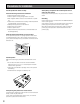
■ HDD Unit (1) Put the cushion between the front cover and HDD canister. To install a hard disk drive in the extension unit, it is necessary to assemble an HDD unit (encase the hard disk drive in the HDD canister). The HDD unit is designed to easily install/remove the hard disk drive in/from the extension unit. Contact your dealer about purchasing, installing, and replacing the hard disk drives.
1 Fix both sides of the hard disk drive with the dedicated HDD canister using the 4 provided screws for HDD canister installation. Tightening torque for the screws: 0.49 N·m (5 kgf·cm) (use a low-torque powered screwdriver or a torque screwdriver) HDD fixing screw HDD fixing screw 2 Fix the bottom of the hard disk drive with the HDD canister using the 2 provided screws for HDD canister installation. Tightening torque for the screws: 0.
■ Handle the hard disk drives The HDD units can be easily installed/removed in/from the HDD slots inside the front cover. Contact your dealer about purchasing, installing, and replacing the hard disk drives. Important: • Hard disk drives are precise devices. Note the following when handling them. • They are vulnerable to vibration. Handle them with care. • Before touching a hard disk drive, release static electricity from your body using an anti-static grounding strap, etc.
● Install the HDD units It is possible to install the HDD units without stopping the operation. Refer also to the manuals provided with the recorder. • When the inserted hard disk drive is formatted, it will be recognized as the hard disk drive for playback use only. In this case, the HDD status indicator will blink green. To use it for recording, follow the instructions from step 4.
11 Move the underscore mark below "YES" using the arrow button (left or right), and then press the [SET] button. The installed HDD unit will be recognized as the HDD units for recording use. ● Install (link) all the HDD units in the extension unit at the same time It is possible to make all the HDD units in the extension unit available (make them linked) at the same time. Refer also to the manuals provided with the recorder. 1 Install the HDD units in the extension unit.
6 Press the arrow button (up or down) repeatedly until the "Link EXT" indication is displayed. 7 Move the underscore mark below "YES" using the arrow button (left or right), and then press the [SET] button. 8 Select the HDD slot number to which the HDD unit is to be inserted using the arrow button (up or down), and then press the [SET] button.
6 Move the underscore mark below "YES" using the arrow button (left or right), and then press the [SET] button. 7 Select the device from which the HDD unit is to be removed (network disk recorder: MAIN, extension unit x: EXTx) using the arrow button (up or down), and then press the [SET] button. 10 Remove the HDD units from the extension unit. (1) Hold down the removal knob on the HDD unit. (2) Pull the lever up. (3) Pull the HDD unit out from the HDD slot.
● Remove all the HDD units in the extension unit at the same time It is possible to remove (link off) all the HDD units in the extension unit. Refer also to the manuals provided with the recorder. 1 After inserting the provided key into the key hole on the front cover, push and turn it to the right to open the front cover. 7 Select the extension unit (EXT#) to be removed using the arrow button (up or down), and then press the [SET] button.
10 Close the front cover and lock it by pushing and (1) turning the key to the left. Keep the key in a safe place. (2) (2) 4 (1) 1 1 Check the disk information. Determine the operational mode using the [RAID] switch. S: Single mode (Default) R5: RAID 5 mode R6: RAID 6 mode The following can be checked on the "Disk information" page on the setup menu of the recorder. Refer to the manuals provided with the recorder for further information.
■ Data recovery (in the RAID 5/RAID 6 mode) If a hard disk drive failure occurs in the RAID 5 or RAID 6 mode, the error display will appear as shown in the following table. In the RAID 5 mode, it is possible to read data on the other hard disk drives and recover data even when a single hard disk drive becomes faulty (1DOWN). In the RAID 6 mode, it is possible to read data on the other hard disk drives and recover data even when 2 hard disk drives become faulty (2DOWN).
● Replacement of a faulty hard disk drive in the RAID mode In the RAID 5 mode, it is possible to read data on the other hard disk drives and recover data even when a single hard disk drive becomes faulty (1DOWN). In the RAID 6 mode, it is possible to read data on the other hard disk drives and recover data even when 2 hard disk drives become faulty (2DOWN). 2 Insert a new HDD unit into the HDD slot respective to the HDD access indicator.
Troubleshooting Check the following before requesting repair. Contact a dealer if a problem cannot be solved even after checking and trying the solution or if a problem is not described below, or when having a problem with installations. Problem Check item/Remedy Check if the power plug is properly connected to the AC outlet. Power is not turned on. The error indicator blinks orange. The unit stops because of the thermal error. The extension unit is not recognized.
Problem Check item/Remedy Make sure that the HDD unit is inserted all the way into the HDD slot. The hard disk drive is not recognized. The HDD status indicator does not light. Was another HDD unit inserted to the HDD slot before completing the recognition process of the other HDD unit? Remove the unrecognized HDD unit and insert it after the current recognition process is complete. The hard disk drive is faulty. The HDD unit is not recognized even though the HDD status indicator is lit.
Problem Check item/Remedy The HDD status indicator lights orange and red alternately even when no recording or playback is being performed. Make sure that recovery of data in the RAID 5/RAID 6 mode is not being processed. The power cord insulation is damaged. The power cord, plug and connectors are worn out. This may result in electric shock or a fire. Remove the power plug from the AC outlet immediately, and refer to qualified service personnel. The power cord, plug and connectors get hot during use.
Specifications • General Power source: Power consumption: Ambient operating temperature: Ambient operating humidity: Maximum operating altitude: Dimensions: Mass: NTSC model: 120 V AC, 60 Hz PAL model: 220 V AC to 240 V AC, 50 Hz 130 W 5 °C to 45 °C {41 °F to 113 °F} 5 % to 90 % (non condensing) 2 000 m {6 562 feet} above sea level 430 mm (W) x 132 mm (H) x 400 mm (D) {16.93 inches (W) x 5.20 inches (H) x 15.
Information on Disposal for Users of Waste Electrical & Electronic Equipment (private households) This symbol on the products and/or accompanying documents means that used electrical and electronic products should not be mixed with general household waste. For proper treatment, recovery and recycling, please take these products to designated collection points, where they will be accepted on a free of charge basis.