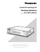
Central Processing Unit Operating Instructions Model No. WJ-MPU955A FAN AL ARM OPERAT E HDD ACTIVE Central Process ing Unit W J-MPU9 55A Before attempting to connect or operate this product, please read these instructions carefully and save this manual for future use. No model number suffix is shown in this manual.
We declare under our sole responsibility that the product to which this declaration relates is in conformity with the standards or other normative documents following the provisions of Directives EEC/73/23 and EEC/89/336. Wij verklaren als enige aansprakelijke, dat het product waarop deze verklaring betrekking heeft, voldoet aan de volgende normen of andere normatieve documenten, overeenkomstig de bepalingen van Richtlijnen 73/23/EEC en 89/336/EEC.
For Canada This Class A digital apparatus complies with Canadian ICES-003. For U.S.A NOTE: This equipment has been tested and found to comply with the limits for a Class A digital device, pursuant to Part 15 of the FCC Rules. These limits are designed to provide reasonable protection against harmful interference when the equipment is operated in a commercial environment.
Important Safety Instructions 1) Read these instructions. 2) Keep these instructions. 3) Heed all warnings. 4) Follow all instructions. 5) Do not use this apparatus near water. 6) Clean only with dry cloth. 7) Do not block any ventilation openings. Install in accordance with the manufacturer's instructions. 8) Do not install near any heat sources such as radiators, heat registers, stoves, or other apparatus (including amplifiers) that produce heat.
Limitation of Liability THIS PUBLICATION IS PROVIDED "AS IS" WITHOUT WARRANTY OF ANY KIND, EITHER EXPRESS OR IMPLIED, INCLUDING BUT NOT LIMITED TO, THE IMPLIED WARRANTIES OF MERCHANTABILITY, FITNESS FOR ANY PARTICULAR PURPOSE, OR NON-INFRINGEMENT OF THE THIRD PARTY’S RIGHT. THIS PUBLICATION COULD INCLUDE TECHNICAL INACCURACIES OR TYPOGRAPHICAL ERRORS. CHANGES ARE ADDED TO THE INFORMATION HEREIN, AT ANY TIME, FOR THE IMPROVEMENTS OF THIS PUBLICATION AND/OR THE CORRESPONDING PRODUCT (S).
CONTENTS Important Safety Instructions ........................................... 4 Limitation of Liability ........................................................ 5 Disclaimer of Warranty .................................................... 5 Trademarks and Registered Trademarks......................... 5 Network Security .............................................................. 5 Software License (Licence) ............................................. 5 Preface .....................................
■ Alarm Arming Control ............................................. 64 ■ To Operate Alarm-related Camera (ACK) .............. 65 ■ To Cancel Alarms ................................................... 65 ■ Alarm History Table ................................................ 66 WJ-HD300A Series Control .......................................... 67 ■ Recorder Selection ................................................. 67 ■ Displaying WJ-HD300A Series SETUP MENU .......
Preface • Central Processing Unit WJ-MPU955A is the main component of WJ-SX650 512 x 64 Full Matrix System and GX System that are network-based. • This document describes how to operate Central Processing Unit WJ-MPU955A from the Panasonic Ethernet controllers. Note: GX System is supported by NTSC model only. Features You can select one of the following systems supported by WJ-MPU955A.
Precautions • Refer all work related to the installation of this appliance to qualified service personnel or system installers. • Do not block the ventilation opening or slots on the cover. To prevent the appliance from overheating, place it at least 5 cm {2 inches} away from the wall. • Do not drop metallic parts through slots. This could permanently damage the appliance. Turn the power off immediately and contact qualified service personnel for service. • Do not attempt to disassemble the appliance.
Document Convention This document uses the following convention when describing the use and operation of this unit.
References This document will provide the product information about WJ-SX650 512 x 64 Full Matrix System and GX System.
This page intentionally left blank.
FEATURES OF WJ-SX650 512 x 64 FULL MATRIX SYSTEM AND GX SYSTEM 13
Main Features ■ Operator Functions ■ Video Camera Functions ● Operator Area Changes ● Camera Control The system can be divided into multiple areas (up to 64), and an operator can change from one area to another if they have the necessary permission. The system provides operators with the camera control functions. The supported functions are: pan, tilt, zoom, focus, and iris. ● Operator Log On and Off ● Camera Operation Operators are assigned a user ID and password by a system administrator.
■ Tour Sequences ■ Event Operations ● Program the Tour Sequences The function allows administrators to program system events. The event function currently supports following operations: This function allows administrators to program tour sequences, and store them in the system database. The WJ-MPU955A can execute 20 tour sequence steps in around one second.
GX System Examples (NTSC Model Only) ■ Standard System Standard System contains one CPU. It can handle up to 256 encoder devices, up to 64 decoder devices, one administration station, and up to 64 system controllers. The IP addresses in the following diagram are the default addresses of the CPU network ports. Note: MPEG2 Encoder (WJ-GXE900) and MPEG2 Decoder (WJ-GXD900) support the NTSC model only. 192.168.1.
■ Redundant System Redundant System requires two CPUs. It can also handle up to 256 encoder devices, up to 64 decoder devices, one administration station, and up to 64 system controllers. 192.168.1.10 TRIGGER OUT ALARM IN RESET ON OFF POWER 4 3 2 1 G 4 3 2 1 GGV + – G 100BASE-TX TERM RS-485 4 3 2 ON 1 VIDEO IN VIDEO OUT AUDIO IN OFF SIGNAL GND WJ-GXE900 1000BASE-T 100BASE-TX 2 1 4 3 V+ – G 2 1 4 3 ON QUAD MIX RESET SIGNAL GND OFF AUDIO OUT Switching HUB VIDEO OUT POWER 192.
Available System Controllers Ethernet Controllers • WJ-MPU955A supports Panasonic Ethernet controllers. • Up to 64 system controllers are connectable in the system. • IP addresses will be automatically provided to each system controller during the communication with the CPU.
WJ-SX650 512 x 64 Full Matrix System Example This system contains one CPU. The CPU can handle up to four SX650 sub nodes and two SX650 bridge nodes, one admin console and up to 64 system controllers. Each sub node should equip one Network Board WJ-PB65E01 to communicate with the CPU through the Ethernet wiring.
This page intentionally left blank.
DETAILED PRODUCT DESCRIPTION 21
Major Operating Controls and Their Functions ■ Layout The following diagrams are the front panel and the rear panel of the WJ-MPU955A.
■ Panel Details q Operation Indicator (OPERATE) The operation indicator is on when the power of the WJ-MPU955A is turned on and the OPERATE switch is pressed. The operation switch of the CPU is located behind the front panel. w Screws These screw are removed to detach the front panel. e Fan Alarm Indicator (FAN ALARM) FAN ALARM indicator shows the cooling fan status. This indicator lights when the cooling fan has a trouble, and keeps lighting until the power is turned off.
This page intentionally left blank.
INSTALLATIONS 25
Installations WARNING The installations described in the diagram should be made by qualified service personnel or system installers. ■ Mounting into the Rack The CPU (WJ-MPU955A) should be mounted into the rack as shown in the following diagram. Here are the steps: 1. Install the rack mounting brackets on both sides of the unit. Using the mounting screws (8 pcs.) for the rack mounting brackets, fix them firmly. Mounting brackets (x2) (Supplied) Mounting screws (x8) (Supplied) 2.
CONNECTION OF GX SYSTEM (NTSC MODEL ONLY) 27
Connection with System Devices In addition to the WJ-MPU955A, other system devices are required in order to form the GX System. ■ Connections and Configurations for Redundant System ■ System Controllers 10BASE-T/100BASE-TX POWER SERIAL ON SIGNAL GND OFF SYSTEM CONTROLLER A system controller is an operator console, and it provides a user interface for operators to interact with the GX System. The system can support up to 64 system controllers.
3. Turn both CPUs on. 4. By using the admin console, click the "Get CPU Status" button. When the admin console asks to set default status, click "Yes" When switching the CPU to Active/Standby By using the admin console, click the "Switch Active CPU" button on the "CPU" screen. The Active CPU reboots automatically, and moves to Standby. The other CPU moves to Active. ● For Automatic Switchover Operation 1.
■ Digital Video Encoder Devices Digital video encoder devices refer to MPEG2 video encoder devices (WJ-GXE900). They connect to the CPU through an Ethernet switching hub in an IP based network. Refer to the Operating Instructions of MPEG2 encoder/MPEG2 decoder. ● Connect with CPU The video encoders connect with the CPU through its Ethernet port and one or more switching hub units. The system can support up to 256 video encoder devices. 192.168.200.
● Setup Encoder Itself In order to communicate with the CPU, the encoder device must also be configured. You can access the encoder device through its Web interface using Microsoft Internet Explorer. Following is an example of the system layout and information to be filled into the table. WJ-GXD900 1000BASE-T 100BASE-TX 2 1 4 3 V+ – G 1 4 3 ON QUAD MIX RESET 2 SIGNAL GND OFF AUDIO OUT VIDEO OUT POWER 192.168.3.
■ Digital Video Decoder Devices Digital video decoder devices refer to MPEG2 video decoder devices (WJ-GXD900). They connect to the CPU through an Ethernet switching hub in an IP based network. Refer to the Operating Instructions of MPEG2 encoder/MPEG2 decoder. ● Connect with CPU The video decoders connect with the CPU through its Ethernet port and one or more switching hub units. The system can support up to 64 video decoder devices.
■ Setup Layer 3 Switching (L3SW) Layer 3 Switching refers to a class of high-performance routers optimized for wire speed Ethernet routing and switching services. It is required to support Internet Group Management Protocol (IGMPv2). Based on the sample described in "Digital Video Encoder Devices" and "Digital Video Decoder Devices", the following table contains Ethernet ports information for the L3SW. Port # IP Address Connection 1 192.168.1.1 Encoder #1,2 2 192.168.2.1 Encoder #3,4 3 192.168.3.
■ Digital Disk Recorders Digital Disk Recorder is the combination of hard disk recorder (a recording device using a hard disk drive to record camera pictures) and video multiplexer. Refer to the Operating Instructions of digital disk recorder for details. ● Connect with CPU The digital disk recorders connect with the CPU through its Ethernet port and one or more switching hub units. The system can support up to 64 video decoder devices.
CONNECTION OF WJ-SX650 512 x 64 FULL MATRIX SYSTEM 35
Connection with System Devices ■ System Controllers Regarding system controllers, the connection and setup are same as the GX system. (Refer to p. 28.) ■ Matrix Switcher WJ-SX650 Series ● Network Board Installation The back panel (OUT X-1) of Video Output Board 1 should be replaced by Network Board WJ-PB65E01. ● Connect with CPU The matrix switchers connect with the CPU through its Ethernet port and one or more switching hub units. This system can support up to six WJ-SX650 SubNodes.
● MODE Switch Settings Each matrix switcher's Video Output Board 1 should be given the unique address by the MODE switch setting. This address and IP address are registered in the admin console, and the CPU assigns the IP address to each matrix switcher based on the admin console database.
● Connect with Each SX650 SubNode via Coaxial Cables *1-1 Video Connection between SubNode 1 and SubNode 3 (Bridge) SubNode 1 SubNode 3 Monitor Output Connectors 1 (Output Board (1)) Camera Input Connecters 1 (Input Board (1)) : : Monitor Output Connectors 16 (Output Board (1)) Camera Input Connecters 16 (Input Board (1)) Monitor Output Connectors 1 (Output Board (2)) Camera Input Connecters 17 (Input Board (1)) : Monitor Output Connectors 16 (Output Board (2)) : Camera Input Connecters 32 (Input
*2-1 Loop-thru Connection between SubNode 1 and SubNode 4 SubNode 1 SubNode 4 VIDEO OUT 1 (Input Board (1)) Camera Input Connecters 1 to 8 (Input Board (1)) VIDEO OUT 2 (Input Board (1)) Camera Input Connecters 9 to 16 (Input Board (1)) VIDEO OUT 3 (Input Board (1)) Camera Input Connecters 17 to 24 (Input Board (1)) VIDEO OUT 4 (Input Board (1)) Camera Input Connecters 25 to 32 (Input Board (1)) VIDEO OUT 1 (Input Board (2)) Camera Input Connecters 1 to 8 (Input Board (2)) VIDEO OUT 2 (Input Boa
*2-2 Loop-thru Connection between SubNode 2 and SubNode 5 SubNode 2 SubNode 5 VIDEO OUT 1 (Input Board (1)) Camera Input Connecters 1 to 8 (Input Board (1)) VIDEO OUT 2 (Input Board (1)) Camera Input Connecters 9 to 16 (Input Board (1)) VIDEO OUT 3 (Input Board (1)) Camera Input Connecters 17 to 24 (Input Board (1)) VIDEO OUT 4 (Input Board (1)) Camera Input Connecters 25 to 32 (Input Board (1)) VIDEO OUT 1 (Input Board (2)) Camera Input Connecters 1 to 8 (Input Board (2)) VIDEO OUT 2 (Input Bo
CONFIGURATION DETAILS 41
Available Configurations Notes: • Normally, maintain the default configuration. • When modifying the configuration, refer to experienced system administrators. ■ Configuration File Modification The system configuration file is referred to as the SYS.INI file. It contains system-wide configuration information, and can be modified by the system administrators through the admin console. (Refer to the Admin Console User's Guide.) The CPU contains default SYS.INI file. (Refer to p. 43.
Default SYS.INI Contents Text appearing in blue is explanatory, and not part of the sys.ini file. Interface section The CPU can incorporate up to three Ethernet network interface cards. [INTERFACES] ***{ Number of interfaces in the system} Numinterfaces=3 The number used here is the number of the Ethernet ports on MPU955A CPU.
Procs section This section tells the system which interface is to be used by certain process files. [PROCS] ***{ Process Interface Assignments } ***{ Format: = } ***{ Set these three to the interface_num of the Ethernet keyboards: } Keybp=1 Mxconts=1 Mxpfw=1 "1" means interface1 in [INTERFACES] section. MPU955A CPU has 3 software processes (listed above) to communicate to a CU950. All processes should use same interface number. Factory default setup is interface "1".
TimeDateFormat=1 ***{ Time-Hour Display format } ***{ Format: TimeHourFormat= } ***{ format 0 - 12 Hour } ***{ format 1 - 24 Hour } TimeHourFormat=0 UNIT section Note: This section should not be changed. [UNIT] ***{ The unit ID should be the same as the one defined in } ***{ the Global Admin database for this unit. } ***{ For single-unit systems, use ID=1. (ID=0 is invalid) } ID=1 LOG section This section sets the frequency with which log files are saved to hard disk.
ALARMTEXTDISPLAY section This section sets up the characteristics of the alarm text - whether alarm text only or alarm and action text. There is a 38 character maximum for alarm text. [ALARMTEXTDISPLAY] ***{ This section is optional. It is not required unless ***{ System defaults are not acceptable. Delete the ***{ single asterisks below to make this section active.
SNTP section Note: This section should not be changed. This section allows changes to Simple Network Time Protocol parameters, if SNTP is implemented. [SNTP] ***{ This section is optional. It is not required unless ***{ System defaults are not acceptable. Delete the ***{ single asterisks below to make this section active. ***{ This section lists user-defined client SNTP values, ***{ sync rates and an external server address.
Default Database Contents (WJ-SX650 512 x 64 Full Matrix System) This section indicates the default contents of sample650.adm (sample database for WJ-SX650 512x64 Full Matrix System) that is included on the CD-ROM. SX650 SUBNODES ID I/F IPA BRIDGE CONTROL OSD SWITCH ALARM Input Output Address 5 6 7 EA 8 1 0 192.168.200.1 – 1-256 – 1-256 1-32 – OFF-OFF-OFF-OFF 00:00:00:00:00:00 2 0 192.168.200.2 – 257-512 – 257-512 1-32 – OFF-OFF-OFF-ON 00:00:00:00:00:00 3 0 192.168.200.
MONITORS ID Area Local Switch Port 1 0 1 SX650 1 2 0 2 SX650 2 3 0 3 SX650 3 4 0 4 SX650 4 5 0 5 SX650 5 : : : : : : : : : : 63 0 63 SX650 63 64 0 64 SX650 64 OPERATORS ID Password Priority Timeout Name Class 100 100 100 00:00:00 Normal 1: Normal 955 955 3 00:00:00 Super 2: Super 49
Database Contents (GX System) (NTSC Model Only) This section indicates the contents of sample.adm (sample database for GX system) that is included on the CD-ROM. GX DEVICES ID I/F IPA EA ENC Input port DEC Output port GXDIN Input port Address A B C 1 0 192.168.1.1 00:00:00:00:00:00 1-4 – – 0 0 1 2 0 192.168.1.2 00:00:00:00:00:00 5-8 – – 0 0 2 3 0 192.168.2.1 00:00:00:00:00:00 9 - 12 – – 0 0 3 4 0 192.168.2.2 00:00:00:00:00:00 13 - 16 – – 0 0 4 5 0 192.168.
CONTROLLERS ID Area Priority Boot File Model IPA EA Port 1 0 3 – WV-CU950 172.18.0.200 00:80:45:0D:D0:01 0 Note: Actual MAC address that is indicated on a product should be entered in the EA field.
DIGITAL RECORDERS ID Logical Model Video Switch 1 52 1 WJ-HD316A GX IPA Unit Address Digital Bitrate Channels Cam 1 1 2 2 3 3 4 4 5 5 6 6 7 7 8 8 9 9 10 10 11 11 12 12 13 13 14 14 15 15 16 – Port 16 172.18.0.60 1 6.
OPERATING PROCEDURES (with WV-CU950) 53
LCD Display Descriptions ■ Default Status (LCD Display After Login) MON 0032 Unit:01 CAM >00512 q Monitor number The number of connected monitor is displayed. w Unit number/Status The number of connected site will be displayed. e Camera number The number of selected camera is displayed. r Input number/Recorder number/Status The numeric input, selected recorder number, or status is displayed. This message is displayed in the following circumstances.
Login and Logout ■ Operation Start (Login) 1. Turn on the power switches of all system components. 2. Turn on the power of system controller. (Refer to the Operating Instructions.) The OPERATE indicator will light up, and the following message will appear on the LCD. Note: If you perform the login procedure after resetting the CPU unit or turning on the power of CPU unit, the LCD display may return to Step 2. In this case, wait for approx. 5 minutes until the CPU unit has been started up.
Monitor Selection and Camera Selection After the login procedure, the following operations are available to control the system. The operation begins with monitor selection. Then, the image of selected camera appears on the active monitor. ■ Monitor Selection 1. Select the desired monitor number by pressing the numeric buttons. The entered number will appear on the LCD. MON 123 Unit:01 CAM 2. Press the MON (ESC) button. When the selected monitor number is correct, <" is displayed. MON 0123
Display Setting for Controller ■ Adjustment of LCD Display and Buzzer You can perform the settings of LCD brightness, LCD contrast, alarm buzzer, or button buzzer. (Refer to WV-CU950 Operating Instructions for how to adjust.
Camera Site Accessories Control ■ Lens Control Note: To return the lens iris to the factory default status, press the A button of 3D joystick unit. Notes: • Check that a specified lens, with motorized zoom/focus functions, is mounted on the camera, and the lens selection (DC/VIDEO) on the camera is set to DC. • Available functions differ depending on cameras. Refer to the Operating Instructions of camera. A 1. Select the desired monitor and camera. (Refer to p. 56 Monitor Selection and Camera Selection.
4. Press the PRESET/PGM PRESET button while holding down the SHIFT button. The preset position will be saved. MON PrgPre:15 CAM 0123 Unit:01 00512 Note: If the entered position number has stored the previous preset position, it will be overwritten by the new one. ■ Wiper Control The following procedure is available when a selected camera (housing) is equipped with a wiper. 1. Select the desired monitor and camera. (Refer to p. 56 Monitor Selection and Camera Selection.) 2. Keep pressing the WIPER button.
■ Defroster Control ■ Auxiliary Control The following procedure is available when a selected camera (housing) is equipped with a defroster. You can control one or two auxiliary control devices. The following procedure is available when an auxiliary control device, such as Receiver WV-RC150, is connected to a system unit. 1. Select the desired monitor and camera. (Refer to p. 56 Monitor Selection and Camera Selection.) ● Operating Procedure 2. Pressing the DEF ON/OFF button.
Camera Function Control ■ Camera Function (Shortcut Function) The following function is available only when specified cameras with the camera function feature are used. This function enables executing camera functions via a shortcut. 1. Select the desired monitor and camera. (Refer to p. 56 Monitor Selection and Camera Selection.) 2. Enter the desired camera function number by pressing the numeric buttons.
Running Sequence ■ Tour Sequence ■ Group Sequence The following functions are available if a Tour Sequence has been previously configured through the admin console. Any Tour Sequence can be assigned to any monitors. The following function is available only if a Group Sequence has been previously established through the admin console. A Group Sequence determines the assignment of monitors and cameras. 1. Select the desired monitor. (Refer to p. 56 Monitor Selection.) 1.
Note: You can also return to spot monitoring by selecting a camera. ■ Call Group Preset Refer to p. 78 Menu Function Details for how to operate. Notes: • Group sequences should contain group presets with the same group of monitors. • If two or more group sequences are assigned to the same monitor, only one group sequence can run at a time. • Group sequences do not support the switchover and restore functions.
Alarm Control ■ Example of Alarm Input and Resulting Alarm Activation The following is an example of an alarm input and the resulting alarm activation. ■ Alarm Selection To control alarm behaviors, you need to select a desired alarm number. 1. Select a desired alarm number by pressing the numeric buttons. ● Basic Setup Note: Refer to the Admin Console User's Guide for details on setup. • Alarm Input #1 activates Gseq (Group Sequence) #1 as Alarm Action #0. The Group Sequence has priority 12.
To arm or disarm all alarms Every time you press the ALARM/ALM SUSPEND button while holding down the SHIFT button, all alarms will be armed or disarmed. ■ To Cancel Alarms 1. Perform Step 1 to 2 of p. 64 Alarm Selection. 2. Press the ALM RESET/ALM ALL RESET button to reset the alarm. "Reset" will be displayed on the LCD. MON 0123 ALL Arm CAM 00512 MON CAM 0123 ALLDisarm 00512 Note: To arm or disarm an alarm, activate Allow Disarm for the alarm. (Refer to the Admin Console User's Guide for details.
■ Alarm History Table There are 1000 alarm records stored in chronological order in 125 pages of table. 1. Select a desired monitor. (Refer to p. 56 Monitor Selection.) 2. Press the ALM RECALL button. "AlarmHist" will appear on the LCD, and the ALARM HISTORY table will be displayed on the active monitor.
WJ-HD300A Series Control Central Processing Unit WJ-MPU955A can control Digital Disk Recorder WJ-HD300A Series. MON 0123 Unit:01 CAM >00512 ■ Recorder Selection To control this recorder, you need to perform the operations described in Recorder Selection. You can select a recorder by performing either of the following. • Recorder auto selection • Recorder manual selection ● Recorder Auto Selection 1. Select a camera whose picture you wish to play back. (Refer to p. 56 Camera Selection.) 2.
• To display the spot playback picture, press the numeric button corresponding to the desired channel number, then press the ENTER button. Then, the active camera number will appear on the LCD. ● Electronic Zooming (EL-ZOOM) Playback images can be electrically zoomed besides a camera's optical zooming. 1. Select the recorder. (Refer to p. 67 Recorder Selection.) MON 0123 Unit:01 DVR >00512 • To select the next channel number, press the + button.
● Manual Recording Note: While holding down the SHIFT button, the LCD display will become as follows. 1. Select the recorder. (Refer to p. 67 Recorder Selection.) 2. Press the REC button. Recording will start. 3. To stop the recording, hold down the REC button for 2 seconds. Search Mode /HD300 Nr-A Cp-A Cpy1 Cpy2 F1 F2 F3 F4 Note: Refer to the Operating Instructions of recorder for details and other recording modes. ● Marking 1. Select the recorder. (Refer to p. 67 Recorder Selection.) 2.
Available buttons and functions (Text information) CAM (SET), MON (ESC), or EXIT button: Returns to the upper menu. Note: Text editing is not available. Available buttons and functions (DATA COPY window) JogDial clockwise: Increments a parameter. JogDial counterclockwise: Decrements a parameter. CAM (SET) button: Executes the selection and starts data copy. (If "OK" is selected) / Cancels the selection and returns to the upper menu.
7. Select a desired recording event by performing one of the following. • Move the 3D joystick controller to up or down. • Rotate the JogDial clockwise or counterclockwise. • Press the + or – button. Note: To move to the next or previous page, perform either of the following. • Move the zoom wheel controller to the right or left. • Rotate the shuttle ring clockwise or counterclockwise. 8. Press the PLAY button. The playback of selected recording event will start. 9.
● VMD search Recording events will be searched by the date and time when a camera detected the brightness-level change. Then, a result list or a thumbnail will be displayed. For playback, you will select a time and date displayed on the result list or thumbnail. Filtering is available by camera channel, date-and-time, detection area or search mode. 1. Select the recorder. (Refer to p. 67 Recorder Selection.) 5. Press the CAM (SET) button. The motion detection area setup window will be displayed. 2.
Note: To delete the motion detection area, select "DELETE AREA" on the status bar by rotating the JogDial or pressing the +/– button. Then, move the "+" mark to the desired area with the joystick, and press the CAM (SET) button. 14. Select a desired detection mode with the 3D joystick, and select a desired parameter by performing either of the following. • Rotate the JogDial clockwise or counterclockwise. • Press the + or – button. 10.
Note: To move to the next or previous page, perform either of the following. • Move the zoom wheel controller to the right or left. • Rotate the shuttle ring clockwise or counterclockwise. 4. Press the PLAY button. The playback of selected recording event will start. 5. To exit the search mode, press the MON (ESC) or EXIT button. The live image will be displayed again on the monitor.
■ System Function 1. Select the recorder. (Refer to p. 67 Recorder Selection.) WJ-HD300A Series SETUP MENU will appear on the active monitor, and "B" mark will light up beside "On". The following functions and buttons are valid in SETUP MENU. 2. Enter the desired function number. 3. Press the CAM FUNC/SYS FUNC button while holding down the SHIFT button. The system function of recorder will be executed.
● Disk Selection You will specify a disk of recorder for search playback. 1. Select the recorder. (Refer to p. 67 Recorder Selection.) 2. Press the MENU button repeatedly repeatedly until "HD300 DiskSelect" appears on the LCD. Note: To cancel the setting and exit "HD300 A – B repeat", press the MON (ESC) or EXIT button. The LCD display will return to the default status. 3. During playback, press the F1 button at the point you wish to start playback. The playback start point (A) will be set.
Menu Function Descriptions ■ Menu Functions No. Function 001 Camera Setup 002 Auto Mode 003 BW Mode 004 Patrol Control 005 Group Preset 006 OSD Control 007 Digital Output 008 Alarm Status 009 Video Loss Status 010 System Status 011 Video Loss History 012 Area Change 013 Operator ID 014 Controller ID 015 System Version ■ To Recall Menu Functions 4. To exit the menu, press the EXIT or MON (ESC) button. The LCD display will return to the default status. 1.
Menu Function Details ■ Camera Setup Notes: • The following function requires the use of cameras supporting this function. • The details on the setup menu differ depending on camera models. Refer to WV-CU950/650 Operating Instructions and the Operating Instructions of camera for available controls on the camera setup menu. Available buttons and functions F1: Seq Activates the sequence mode. F2: Sort Activates the sort mode. F3: Pan Activates the auto pan mode. F4: Patrol Activates the patrol mode. 1.
■ Patrol Learn ■ OSD Control 1. Select a desired monitor and camera. (Refer to p. 56 Monitor Selection and Camera Selection.) 1. Select a desired monitor. (Refer to p. 56 Monitor Selection.) 2. Display "Patrol" menu. (Refer to Step 1 and 2 of p. 77 To Recall Menu Functions.) 2. Display "OSD" menu. (Refer to Step 1 and 2 of p. 77 To Recall Menu Functions.) Patrol : Start Stop 004 3. Press the F1 (Start) button. The patrol learn setup will start. : Cam Gen 006 Mon 3.
■ Alarm Status Table ■ Video Loss Status Table The table shows the alarm statuses. The table shows the video loss detection statuses. 1. Select a desired monitor. (Refer to p. 56 Monitor Selection.) 1. Select a desired monitor. (Refer to p. 56 Monitor Selection.) 2. Display "AlmStat" menu. (Refer to Step 1 and 2 of p. 77 To Recall Menu Functions.) AlmStat: On Off 008 VL Stat: On Off 009 Blk Blk 3. Select a desired function by pressing one of the F1 to F3 buttons.
■ System Status Table The table shows the system status in real time. 1. Select a desired monitor. (Refer to p. 56 Monitor Selection.) 2. Display "SysStat" menu. (Refer to Step 1 and 2 of p. 77 To Recall Menu Functions.) SysStat: On Off 010 Notes: • To display the first page of table, press the + button while holding down the SHIFT button. • To display the last page of table, press the – button while holding down the SHIFT button. 5. To exit the SYSTEM STATUS table, perform either of the following.
4. To display the next page, press the + button. To display the previous page, press the – button. ■ Controller ID You can check your System Controller ID as follows. Notes: • To display the first page of table, press the + button while holding down the SHIFT button. • To display the last page of table, press the – button while holding down the SHIFT button. 5. To exit the VIDEO LOSS HISTORY table, perform either of the following. • Select a camera. (Refer to p. 56 Camera Selection.
APPENDIX 83
Troubleshooting Before asking for technical support, please check the following symptoms and their possible causes and solutions. If the solutions below do not solve the problem, or the symptom is not listed below, contact your installer or sales representative. Power Related Failure Symptom The power cord insulation is damaged. The power cord, connector, or power plug are hot-damaged. Possible cause / Possible solution Reference The power cord, connectors, or power plug are damaged.
System Controller-Related Problems Symptom WV-CU950 controller fails to start. LCD shows: "Connecting to Main CPU…" Possible cause / Possible solution Check the network connection between the CPU and CU950 controller. Check the controller database and make sure it has the correct controller Ethernet address. Reference Admin Console User's Guide Encoder and Decoder-Related problems (NTSC model only) Symptom The encoder or decoder does not start up normally.
Specifications Power Supply Power Consumption: Controllable Encoders (NTSC model only): Controllable Decoders (NTSC model only): Ethernet Ports: RS-232C Port: Ambient Operating Temperature: Ambient Operating Humidity: Dimensions (excluding rubber feet and projections): Weight: NTSC model: 120 V AC, 60 Hz PAL model: 220 V - 240 V AC, 50 Hz 60 W 256 Encoders 64 Decoders 10Base-T/100Base-TX, 8-conductor modular jack (x3) System controller* (1 port), encoder and decoder control (1 port)**, other (1 port) * Ma
For U.S., Canadian and Puerto Rican fields: Panasonic System Solutions Company, Unit Company of Panasonic Corporation of North America Security Systems www.panasonic.com/security For customer support, call 1.877.733.3689 For European and other fields: Matsushita Electric Industrial Co., Ltd. Osaka, Japan http://panasonic.net Executive Office: Three Panasonic Way 2H-2, Secaucus, New Jersey 07094 Zone Office Eastern: Three Panasonic Way, Secaucus, New Jersey 07094 Central: 1707 N.