Digital Disk Recorders Network Setup Instructions Model Nos.
CONTENTS Preface ............................................................................................................................ 4 Features ...................................................................................................................... 4 Downloading/transmitting images ............................................................................... 4 Event notification function ...........................................................................................
Preface Features It is possible to perform the settings or operate the unit using a PC when this unit is connected to a network. The following functions are available when using a PC via a network as well as the functions operable on the buttons on the front panel of the unit. Refer to the Network Operating Instructions (pdf) on the provided CD-ROM for further information about the available functions.
System requirements for a PC It is recommended to operate this unit using a PC that meets the following system requirements. OS Microsoft® Windows® 2000 Professional SP4 Microsoft® Windows® XP Professional or Home Edition SP1 Computer IBM PC/AT Compatible CPU Pentium IV 1.4GHz or faster Memory 256 MB or more Monitor 1024 x 768 pixels or more, 16-bit HIGH colour or better Network Interface 10/100Mbps Network interface card must be installed Web Browser Microsoft® Internet Explorer 5.5SP2, 6.
Preparations Connections When connecting this unit to a PC, the required hardware and cables are different depending on the system configuration. Prepare before starting connection. Connecting this unit and a PC directly. Connecting this unit to a PC directly using a LAN cable.
Performing network settings In case of the following network environment, it is not necessary to perform network settings. It is possible to perform the settings or operate this unit using a web browser after completing the connection. IP Address: 192.168.0.2 - 192.168.0.249, 192.168.0.251 - 192.168.0.254 Subnet Mask: 255.255.255.0 Gateway Address: 192.168.0.1 When the network settings are different from the settings above, perform the network settings of this unit and the PC.
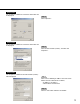
Screenshot 2 The control panel will be displayed. Step 2 Click the "Network and Internet Connections" icon. Screenshot 3 The "Network and Internet Connections" window will be displayed. Step 3 Click "Network Connections". Screenshot 4 The "Network Connections" window will be displayed. Step 4 Double click "Local Area Connection".
Screenshot 5 The "Properties" window of "Local Area Connection" will be displayed. Screenshot 6 The "Properties" window of "Local Area Connection" will be displayed. Screenshot 7 The "Properties" window of "Internet Protocol (TCP/IP)" will be displayed. Step 5 Click "Properties". Step 6 Click "Internet Protocol (TCP/IP)", and then click "Properties". Step 7 Click "Use the following IP address" and enter the IP address and the subnet mask as follows; • IP Address: 192.168.0.9 • Subnet Mask: 255.255.255.
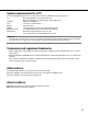
About network security of this unit Equipped security functions q Access restrictions by the host authentication and the user authentication It is possible to restrict users from accessing this unit by setting the host authentication and/or the user authentication to on. (page 69) w Access restrictions by changing the HTTP port It is possible to prevent illegal access such as port scanning, etc. by changing the HTTP port number.
Display the operation window How to display the operation window Start up the PC and operate this unit using the installed web browser. The operation window will be displayed in the following procedure. Screenshot 1 Start just after the PC is started up. Step 1 Start up the web browser. Screenshot 2 The web browser will start up and the set web site will be displayed. Step 2 Enter the IP address set to this unit in the address box, and press the enter key.
Screenshot 3 The user authentication window will be displayed. This window will not be displayed when "OFF" is selected for "User Authentication" on the "System" menu. Step 3 Enter the user name and password registered on this unit. Important: • Refer to a system administrator for the set user name and password. Refer to page 83 for the descriptions of how to register users. • The default user name and password are as follows. User Name: ADMIN Password: 12345 Screenshot 4 The top page will be displayed.
About the operation window Top page [Setup] tab Status display area Current time/play time displayed area [Control] tab Image display area Playback point operation area [Cam] tab [HDD] tab [Control] tab (page 14) The switcher functions such as switching camera channels or displaying sequentially, are operable on this page. Search results or log information will also be displayed on this page. [Setup] tab (page 15) Operations for setup of this unit can be performed on this page.
[Control] tab [Sequence] button Camera images to be displayed will be switched by clicking this button. Camera images will be displayed sequentially according to the settings performed in advance. [EL-Zoom] box Camera images will be displayed in the portion of the clicked zoom ratio button. Log display area [Camera Select] buttons Images from the selected camera channel will be displayed with a spot display on the image display area by clicking one of these buttons.
[Setup] tab [Recording] button The menu for the recording settings will be displayed. Perform the basic recording settings and emergency recording with this menu. Refer to page 30 for further information about this menu. [Event] button The menu for the settings of actions at event occurrence for each event type (terminal alarm, motion detection alarm, video loss alarm and command alarm) will be displayed. Refer to page 34 for further information about this menu.
Status display area w e r q q The status of a live/playback image will be displayed. [LIVE]: Indicates that a live image is being displayed. [SEQ]: Indicates that a live image is being displayed in the sequential display mode. [Playback]: Indicates that a playback image is being displayed. [Reverse playback]: Indicates that a reverse playback image is being displayed. [Fast playback]: Indicates that a fast playback image is being displayed.
Playback point operation area q w e q Indicates the start time and the end time of a download. (Refer to the Network Operating Instructions (pdf).) w [GO TO DATE] button Indicates the time and date of a marked point. Use this button to designate a desired time and date of a recorded image to be played. (Refer to the Network Operating Instructions (pdf).) e [GO TO LAST] button Skips to the latest recorded time of a recorded image from the currently displayed camera channel and plays it.
[REC] box The recording button and the recording stop button will be displayed when the button is clicked. Displaying the recording button and the recording stop button will be unavailable when the button is clicked. [Recording] button: Starts manual recording. [Stop recording] button: Stops manual recording. Notes • It is possible to switch between all channels or the channel currently displayed in the web browser window to be selected for manual recording by performing the settings.
Setup Performing each setting item on the setup menu should be completed in advance to operate this unit. Each setting item on the setup menu can be performed on the setup page. Setting the following items are available on this page. SETUP MENU chart Setup menu Description Page Maintenance REC Rate Status Recording rate in each recording mode and image quality for each camera channel will be displayed in list form.
Setup menu Description Page Schedule Time Table Make timetables of operation for each day of the week, and assign recording action programs and event action programs to each timetable. 47 Special Days Assign timetables for special days apart from other days of the week. 50 Monitor 1 Settings for the image switching such as the sequential operation or for displaying the login window on monitor 1 can be performed.
Setup menu Description Page Network SNMP Setup Settings for SNMP can be performed. Set this item to check the status of the server by connecting to the SNMP server. 72 Network NTP Setup Set this item when adjustment of time is required to be set with the NTP server such as when setting the NTP server address or time zones. 73 Network FTP Setup Settings for the FTP server can be performed.
Basic operation with the [Setup] Tab [Screenshot 1] Start operation after the top menu is displayed. [STEP 1] Click the [Setup] tab. [Screenshot 2] The [Setup] tab will be displayed. [STEP 2] Click a button on the [Setup] tab.
[Screenshot 3] The submenus respective to the clicked button on the [Setup] tab will be displayed. [STEP 3] Click the desired submenu on the [Setup] tab. Submenu [Screenshot 4] The setting page of the selected submenu will be displayed in the image display area. [STEP 4] Perform the settings for each item. Click the [SET] button after completing the settings. When the [CLEAR] button is clicked, the content of the setting will be cleared.
Settings for maintenance [Maintenance] Settings for the hard disk can be performed. Checking the recording rate or image quality for each camera channel is available. Confirmation of recording rate and image quality for each camera channel [REC Rate Status] Recording rate in each recording mode for each camera channel will be displayed in list form. Screenshot 1 Start operation after the submenu of the maintenance menu is displayed by clicking the [Maintenance] button in the [Setup] tab.
Confirmation of available hard disk space [Disk Information] Available disk space for the following disks will be displayed: built-in hard disk (normal recording area, event recording area and copy area), extension unit (EXT1 - 7), DVD-RAM disk, CD-R disk or DVD-R disk connected to the copy port on the rear panel (COPY1 and COPY2). Refer to the network operating instructions on the provided CD-ROM for further information about the built-in hard disk of this unit.
Confirmation of version information [Version Information] Version information of the software and hardware will be displayed. Screenshot 1 Start operation after the submenu of the maintenance menu is displayed by clicking the [Maintenance] button in the [Setup] tab. (page 15) Step 1 Click "Version information". Screenshot 2 The "Version information" menu will be displayed. Step 2 Version information of the software and hardware, and MAC address will be displayed.
Settings for actions when the available hard disk space is running out [Disk End Mode] Settings for actions (overwrite/stop recording) when the available disk space of the built-in hard disk (normal recording area, event recording area and copy area), DVD-RAM disk, CD-R disk or DVD-R disk connected to the copy port on the rear panel (COPY 1 and COPY 2) has run out can be performed.
Warning settings for available hard disk space [Disk Capacity] Performing the settings for the warning action should be done when each available space of the built-in hard disk (normal recording area, event recording area, copy area), DVD-RAM disk, CD-R disk or DVD-R disk connected to the copy port on the rear panel (COPY 1 and COPY 2) reaches the set level. Important: When "CONTINUE" is selected, a warning will not be issued.
Deletion of image data on the hard disk [Data Delete] Image data on the built-in hard disk will be deleted. The two ways to delete data are auto deletion and manual deletion. Initialization (format) of a DVD-RAM disk can be also performed on this menu. Screenshot 1 Start operation after the submenu of the maintenance menu is displayed by clicking the [Maintenance] button in the [Setup] tab. (page 15) Step 1 Click "Data Delete". Screenshot 2 The "Data Delete" menu will be displayed.
Functions for recording [Recording] Perform the settings for recording. Perform the basic settings for recording and the settings for emergency recording. Basic settings for recording [Recording Setup] Perform the basic settings for recording. Screenshot 1 Start operation after the submenu of the recording menu is displayed by clicking the [Recording] button in the [Setup] tab. (page 15) Step 1 Click "Recording setup". Screenshot 2 The "Recording setup" menu will be displayed.
Setup Item ■ Embedded REC (Title) ■ Recording Select ON or OFF to determine whether or not to record a displayed camera title together as a part of the recorded image. ON: Record camera titles together as a part of the recorded image. OFF: Does not record camera titles. Select ON or OFF to record or not record. ON: Recording will be performed. OFF: No recording will be performed. Important: • When OFF is selected for this setting, no recordings will be performed.
Settings for emergency recording [Emergency REC] Perform the settings for emergency recording such as recording time or recording rate. Refer to the provided operating instructions for further information about emergency recording. Screenshot 1 Start operation after the submenu of the recording menu is displayed by clicking the [Recording] button in the [Setup] tab. (page 15) Step 1 Click "Emergency REC". Screenshot 2 The "Emergency REC" menu will be displayed. Step 2 Perform the settings for each item.
Setup Item ■ Resolution ■ Auto Copy Select a resolution for emergency recording from the following. FRAME 3D ON: High resolution (720 x 576) with the motion blur compensation FRAME 3D OFF: High resolution (720 x 576) FIELD: Standard resolution (720 x 288) SIF: Low resolution (360 x 288) Select ON or OFF to set whether or not to automatically copy images recorded by emergency recording onto the copy area on the built-in hard disk or DVD-RAM disk.
Functions for events [Event] Perform the settings for event actions of each event type (motion detection, video loss, terminal alarm and command alarm). Refer to the provided operating instructions for further information about each event type. Basic settings for event actions [Event Setup] Perform the settings for event actions such as alarm output duration and buzzer duration of each camera channel for each event type (motion detection, video loss, command alarm and terminal alarm).
Screenshot 3 The window for the settings of the event action for each event type will be displayed. Step 3 Perform the settings for each item. Refer to the following for further information about the settings for each item. Step 4 Click the [SET] button after completing the settings. Setup Item ■ Priority Assigns priorities to the selected event.
Settings for the motion detection function [VMD Setup] Perform the settings for the auto motion detection area for each camera channel. Up to 4 areas can be set for a camera channel for the detection area. Refer to the provided operating instructions for further information about the auto motion detection function. Screenshot 1 Start operation after the submenu of the event menu is displayed by clicking the [Event] button in the [Setup] tab. (page 15) Step 1 Click "VMD Setup".
Screenshot 3 The "VMD Area Setup"menu will be displayed. Step 5 Press the [i] button to select the sensitivity for the selected area from the following. LOW: Low sensitivity MID: Standard sensitivity HIGH: High sensitivity OFF: No motion will be detected in this area. Step 6 Check a check box next to a desired detection mode to select and perform the settings of the selected detection mode. Refer to page 38 for further information about each recording mode.
Detection mode There are three detection modes as follows. Important: • Activating two or more detection modes simultaneously is not possible. An event action will be performed according to the settings when "motion" is detected in any of the set motion detection areas. A B Any motion will be detected anywhere in the A, B, C, D areas.
Settings for alarm display and alarm suspension [Alarm Setup] Perform the settings for the alarm displaying duration. The alarm display will automatically disappear when the displaying duration has passed. (Alarm Auto Reset) The following will be performed even if OFF is selected for the "Alarm Auto Reset".
Settings for the alarm terminal polarity [Terminal Setup] Select how to supply the signal to the alarm terminal. Screenshot 1 Start operation after the submenu of the event menu is displayed by clicking the [Event] button in the [Setup] tab. (page 15) Step 1 Click "Terminal Setup". Screenshot 2 The "Terminal Setup" menu will be displayed. Step 2 Select polarities for each terminal by clicking the [i] button. N.O.: Signals will be supplied when short-circuited. (Normally Open) N.C.
Settings for the recording/event schedule [Schedule] Perform the settings for the recording schedules of recording and event action by designating a day of the week and time. A day can be divided into up to 6 time zones, and recording programs and event action programs can be assigned to each time zone to create a recording schedule. Up to 4 normal recording programs and up to 4 event action programs can be created. Perform the settings for the recording programs: resolution and recording rate.
Screenshot 2 The "REC Program" menu will be displayed. Step 2 Click the respective [SETUP] button for a desired program to create a recording program. Screenshot 3 The "Schedule Recording Program" menu will be displayed. Step 3 Perform the settings for each item. Refer to page 43 for further information about the settings for each item. Step 4 Click the [SET] button after completing the settings.
Setup Item ■ Resolution ■ Recording Rate and Image Quality for Each Select a resolution for images to be recorded from the following. FRAME 3D ON: High resolution (720 x 576), with blurring compensation FRAME 3D OFF: Standard resolution (720 x 576) FIELD: Standard resolution (720 x 288) SIF: low resolution (360 x 288) Camera Channel Perform the settings for recording rate, image quality and recording duration for each camera channel (only for event pre-recording and event post-recording).
Creating recording programs for an event occurrence [Event PROG Setup] Perform the settings of action mode or alarm mail for each event type (motion detection, video loss, terminal/command alarm). Screenshot 1 Start operation after the submenu of the schedule menu is displayed by clicking the [Schedule] button in the [Setup] tab. (page 15) Step 1 Click "Event Program". Screenshot 2 The "Event PROG Setup" menu will be displayed.
Screenshot 3 The event program menu will be displayed. Step 3 Click the respective [SETUP] button for a desired event to be set. Screenshot 4 The window for selection of the event channel/number will be displayed. Step 4 Click the respective [SETUP] button for a desired event channel/number to be set. Screenshot 5 The setup menu for the event action will be displayed. Step 5 Perform the settings for each item. Refer to page 46 for further information about the settings for each item.
Setup Item ■ Action Mode ■ Serial Notice Perform the settings for the action mode. Refer to the provided operating instructions for further information about each action mode. ACT DET (Activity Detection Mode): Performs only recording, writing an event log and camera movement to a preset position at an event occurrence. Other event actions will not be performed. ALARM (Alarm Mode): Performs every event action according to the settings.
Assignment of recording program and event program after setting the time zone [Time Table] Create recording timetables for each day of the week, and assign recording program and event program to each timetable. Up to 6 recording programs can be created. Screenshot 1 Start operation after the submenu of the schedule menu is displayed by clicking the [Schedule] button in the [Setup] tab. (page 15) Step 1 Click [Time Table]. Screenshot 2 The "Time Table" menu will be displayed.
Screenshot 3 The timetable of the selected day of the week will be displayed. Step 3 Perform the settings for each item. Perform the settings of the following item for each time zone. [START] Set the start time of the time zone. [END] Set the end time of the time zone. Notes: • To copy a timetable that is set for a different day of the week, click the [INPUT] button of "Copy the Other Time Table" at step 3. • To set for two or more days of the week, repeat steps 2 to 4.
Screenshot 4 Returns to the Schedule setup menu. Step 4 The set timetables and the recording programs or the event programs will be applied. Recording programs will be displayed with different colours.
Perform the settings of recording programs for special days [Special Days] Assign timetables to special days aside from other days of the week. Timetables for special days can be set for up to 30 days. Perform the settings to specify dates as special days and apply recording schedule to the specified special days. Screenshot 1 Start operation after the submenu of the schedule menu is displayed by clicking the [Schedule] button in the [Setup] tab. (page 15) Step 1 Click "Special Days".
Settings for switcher function [Switcher] Perform the settings for image switching such as the sequential display setting or the login window display setting to display on monitors 1, 2 or a monitor of a PC connected to the unit via a network. Switcher function of monitor 1 [Monitor 1] Perform the settings for the switcher function of monitor 1. Screenshot 1 Start operation after the submenu of the switcher menu is displayed by clicking the [Switcher] button in the [Setup] tab.
Setup Item ■ Live Sequence ■ Sequence Timing Perform the settings for the sequential display of live images. The following window will be displayed when the [Setup] button is clicked. Perform the settings for each item. Click the [SET] button after completing the settings. Select an image switching way from the following. INT: Switches images according to the settings for the live sequence. EXT: Switches images by signals from an external device.
■ Secret View The secret view is a function that skips camera images displayed with a single screen display on monitor 2 when displaying with the sequential display on monitor 1. Select ON or OFF to determine whether to enable or disable the secret view function. ON: Enables the secret view function. (Camera image displayed with a single screen on monitor 2 on a black screen.) OFF: Disables the secret view function.
Perform the settings to display on a PC monitor with the switcher function [Network] Perform the settings for the switcher function when displaying images on a monitor of a PC connected to this unit via a network. Screenshot 1 Start operation after the submenu of the switcher menu is displayed by clicking the [Switcher] button in the [Setup] tab. (page 15) Step 1 Click "Network". Screenshot 2 The "NW" menu will be displayed. Step 2 Perform the settings for each item.
Setup Item ■ The method of sequence ■ 4 Screen Live Sequence Perform the settings for the sequential display of live images. SPOT: Displays images with the sequential display on a single screen. 4 screen: Displays images with the sequential display on a 4-split screen. Perform the settings for the sequential display when displaying images with the sequential display on 4-split screen. The following window will be displayed when the [Setup] button is clicked. Perform the settings of each item.
Settings for display [Display] Perform the display settings for monitors 1 and 2 connected to the unit. Common setting for monitors [OSD Setup] Perform the common display settings for monitor 1 and monitor 2 such as the settings of camera titles or the settings of the time display position. Screenshot 1 Start operation after the submenu of the display menu is displayed by clicking the [Display] button in the [Setup] tab.(page 15) Step 1 Click "OSD Setup".
Setup item ■ Camera Title Perform the settings for the camera title. The following window will be displayed when the [SETUP] button is clicked. Perform the settings for each item. [Embedded] Enter a camera title to be embedded together (recorded with images) and to be displayed when "ON" is selected for "Title embed" on "Basic recording setup" of "Recording" menu and also for displaying camera titles on monitor 1 (page 31). Enter up to 16 alphanumeric characters for a camera title.
Perform the display settings for monitor 1 [Monitor 1] Select ON or OFF to determine whether to display the time, camera title and alarm display on monitor 1 or not. Screenshot 1 Start operation after the submenu of the display menu is displayed by clicking the [Display] button in the [Setup] tab. (page 15) Step 1 Click "Monitor 1". Screenshot 2 The "Monitor 1" menu will be displayed. Step 2 Perform the display settings for monitor 1.
Perform the display settings for monitor 2 display [Monitor 2] Perform the display settings for monitor 2 such as the task bar style, the time display position and the camera title display, etc. Screenshot 1 Start operation after the submenu of the display menu is displayed by clicking the [Display] button in the [Setup] tab. (page 15) Step 1 Click "Monitor 2". Screenshot 2 The "Monitor 2" menu will be displayed. Step 2 Perform the display settings for the monitor 2.
Settings for communication with other devices [Comm] It is required to apply the same settings, for example, the communication speed, the communication protocol, etc. to the external devices such as a controller connected to the DATA port or the serial port (RS232C). It is also required to perform the network settings such as the IP address, the gateway address, etc. when operating this unit using a PC via a network such as a LAN. Perform the required settings for communicating with external devices.
Screenshot 2 The "Camera Control Setup" menu will be displayed. Step 2 Click the [i] button to select a communication method for each camera channel to control cameras from the following. COAX: Controls cameras with coaxial communication.(CAM 1 - 8 CH are available for the WJ-HD316, CAM 1 - 6 CH are available for the WJ-HD309) PSD: Controls cameras with PS·Data. (CAM 9 - 16 CH are available for the WJ-HD316, CAM 7 - 9 CH are available for the WJ-HD309) RS485: Controls cameras with RS 485 communication.
Settings for PS·Data [PS.Data Setup] Perform the settings for PS·Data. Screenshot 1 Start operation after the submenu of the communication menu is displayed by clicking the [Comm] button in the [Setup] tab. (page 15) Step 1 Click "PS.Data Setup". Screenshot 2 The "PS.Data Setup" menu will be displayed. Step 2 Perform the settings for each item. Refer to page 63 for further information about the settings for each item. Step 3 Click the [SET] button after completing the settings.
Setup item ■ Unit Address (System) ■ Stop Bit A unit address is a unique number to be assigned to each PS·Data device. Each address of the system devices must be unique to identify them when connecting two or more PS·Data compatible devices. Numbers "001" - "099" can be assigned to unit addresses for system devices. Select a stop bit from the following. 1/2 bit ■ Unit Address (Controller) The unit address (controller) is used to control a PS·Data device connected to this unit.
Perform the settings for RS485 [RS485 Setup] Perform the settings for RS485. Screenshot 1 Start operation after the submenu of the communication menu is displayed by clicking the [Comm] button in the [Setup] tab. (page 15) Step 1 Click "RS485 Setup". Screenshot 2 The "RS485 Setup" menu will be displayed. Step 2 Perform the settings for each item. Refer to page 65 for further information about the settings for each item. Step 3 Click the [SET] button after completing the settings.
Setup item ■ Baud Rate Select a communication speed for data transmission with a connected device from the following. 4 800/9 600/19 200 bps ■ Control Camera CH Assign camera channels to the RS485 port 1 and port 2. The following window will be displayed when the [SETUP] button is clicked. Select a port to be controlled from the following for each camera channel. Click the [SET] button after completing the settings. PORT1: Controls from the RS485 port 1. PORT2: Controls from the RS485 port 2.
Perform the settings for SERIAL (RS232C) [RS232C Setup] Perform the following settings for RS232C. Screenshot 1 Start operation after the submenu of the communication menu is displayed by clicking the [Comm] button in the [Setup] tab. (page 15) Step 1 Click "RS232C Setup". Screenshot 2 The "RS232C Setup" menu will be displayed. Step 2 Perform the settings for each item. Refer to page 67 for further information about the settings for each item. Step 3 Click the [SET] button after completing the settings.
Setup item ■ Unit Address (System) A unit address is a unique number to be assigned to each device. Each address of system devices must be unique to identify them when connecting two or more system devices. Numbers "001" - "099" are assigned to unit addresses for system devices for instance. ■ Baud Rate Select a communication speed for data transmission with a connected device from the following. 9 600/19 200/38 400 bps ■ Data Bit Select a data length for communication from the following.
Basic network settings [Network Setup 1] Perform the required basic network settings to operate this unit using a PC via a network such as LAN. Screenshot 1 Start operation after the submenu of the communication menu is displayed by clicking the [Comm] button in the [Setup] tab. (page 15) Step 1 Click "Network Setup 1". Screenshot 2 The "Network Setup 1" menu will be displayed. Step 2 Perform the settings for each item. Refer to page 69 for further information about the settings for each item.
Setup item ■ HTTP Port Number Specify the HTTP port number to be used to send images from the unit. A number from 1 – 65535 is available. It is unnecessary to change it for normal use. ■ User Authentication Select ON or OFF to determine whether to enable or disable the user authentication when the unit is accessed from a PC. When "ON" is selected, the authentication window will be displayed when the unit is accessed from a PC.
Perform the settings for network connection [Network Setup 2] Perform the required network settings to operate the unit using a PC via a network such as LAN. Screenshot 1 Start operation after the submenu of the communication menu is displayed by clicking the [Comm] button in the [Setup] tab. (page 15) Step 1 Click "Network Setup 2". Screenshot 2 The "Network Setup 2" menu will be displayed. Step 2 Perform the settings for each item.
Setup item ■ DHCP ■ DDNS Select ON or OFF to determine whether or not to use the DHCP server. Select "ON" to obtain an IP address, a subnet mask and a gateway address from the DHCP server. Set to "OFF" when entering the addresses above manually. Select ON or OFF to determine whether or not to use the DDNS (Dynamic Domain Name Server). To select ON for the DDNS, it is required to select "MANUAL" or "AUTO" for "DNS". When "ON" is selected, perform the following settings.
Perform the settings for SNMP network [Network SNMP Setup] Perform the settings for the SNMP. Perform the settings for the status check of the server, etc. by connecting the SNMP server. Screenshot 1 Start operation after the submenu of the communication menu is displayed by clicking the [Comm] button in the [Setup] tab. (page 15) Step 1 Click "Network SNMP Setup". Screenshot 2 The "Network SNMP Setup" menu will be displayed. Step 2 Perform the settings for the following item.
Perform the settings for the time adjustment of a network [Network NTP Setup] Perform the settings for the time and date. Screenshot 1 Start operation after the submenu of the communication menu is displayed by clicking the [Comm] button in the [Setup] tab. (page 15) Step 1 Click "Network NTP Setup". Screenshot 2 The "Network NTP Setup" menu will be displayed. Step 2 Perform the settings for the following item.
Perform the settings for the FTP server. [Network FTP Setup] Perform the settings for the FTP server. Perform the required settings for [Network FTP setup] to periodically send images from a camera connected to this unit to a designated FTP server. Screenshot 1 Start operation after the submenu of the communication menu is displayed by clicking the [Comm] button in the [Setup] tab. (page 15) Step 1 Click "Network FTP Setup". Screenshot 2 The "Network FTP Setup" menu will be displayed.
Setup item ■ FTP Server Address ■ Interval Enter an address or name of the FTP server that receives images. To enter an FTP server name, it is necessary to select "MANUAL" or "AUTO" for "DNS". Enter a transmission interval. Select whether it will be "s" (seconds) or "m" (minutes) for the interval unit. ■ User Name Enter a user name (login name) to access the FTP server. Enter up to 32 alphanumeric characters. The available characters are the characters listed below.
Perform the settings for mail notification. [Network Mail Setup] Perform the settings to send e-mails to addresses registered in advance at an event occurrence. Screenshot 1 Start operation after the submenu of the communication menu is displayed by clicking the [Comm] button in the [Setup] tab. (page 15) Step 1 Click "Network Mail Setup". Screenshot 2 The "Network Mail Setup" menu will be displayed. Step 2 Perform the settings for each item.
Setup item ■ Attach Alarm Image ■ User Name Select ON or OFF to determine whether or not to attach an image to an e-mail to be sent at an event occurrence. Enter a user name (login name) to access the POP server. Enter up to 32 alphanumeric characters. The available characters are the characters listed below. ■ Mail Server Address Enter an IP address or a name of the SMTP server to send e-mails to. To enter an SMTP server name, it is necessary to select "MANUAL" or "AUTO" for "DNS".
Perform the settings for the system [System] Perform the settings for the system of this unit. Perform the basic settings for the system [Basic Setup] Perform the settings for the basic operations of this unit. Screenshot 1 Start operation after the submenu of the communication menu is displayed by clicking the [System] button in the [Setup] tab. (page 15) Step 1 Click "Basic Setup". Screenshot 2 The "Basic Setup" menu will be displayed. Step 2 Perform the settings for each item.
Setup item ■ ADMIN Password ■ Priority Set a password for an administrator. Enter 4 to 32 alphanumeric characters. Perform the settings to assign priorities to operate this unit in case two or more users access this unit simultaneously. A priority is followed.: Users with higher priority can operate this unit. Pre-priority: A user who accessed the unit first can operate it regardless of the priorities. Post-priority: A user who accessed the unit last can operate it regardless of the priorities.
■ Auto Copy Perform the settings to copy recorded images automatically to the copy area of the hard disk or the DVD-RAM disk. OFF: Images will not be copied. COPY 1: Images will be copied to the DVD-RAM disk connected to the copy 1 port. COPY 2: Images will be copied to the DVD-RAM disk connected to the copy 2 port. HDD: Images will be copied to the copy area of the hard disk of this unit.
Perform the settings for the time and date [Time & Date Setup] Perform the settings for the time and date. Screenshot 1 Start operation after the submenu of the communication menu is displayed by clicking the [System] button in the [Setup] tab. (page 15) Step 1 Click "Time & Date Setup". Screenshot 2 The "Time & Date Setup" menu will be displayed. Step 2 Perform the settings for each item. Refer to page 82 for further information about the settings for each item.
Setup item ■ Date Format ■ Summer Time (Day Light Saving) Table Select a date format to be displayed from the following. (Example for April 1, 2003) YY.MM.DD: 03.4.1 MMM.DD.YY: APR.1.03 DD.MMM.YY: 1.APR.03 Set the start (ON)/end (OFF) date and time for summer time. The following window will be displayed when the [SETUP] button is clicked. Click the [SET] button after completing the settings. ■ Time Format Select a time format to be displayed from the following.
Registration of a user who operates this unit [User Registration] Register user information such as a user name and password. Screenshot 1 Start operation after the submenu of the communication menu is displayed by clicking the [System] button in the [Setup] tab. (page 15) Step 1 Click "User Registration". Screenshot 2 The "User Registration" menu will be displayed. Step 2 Perform the settings for each item. Refer to page 84 for further information about the settings for each item.
Setup item ■ User Name Enter a user name.Enter 4 to 32 alphanumeric characters for a user name. ■ Password Enter a password. Enter 4 to 32 alphanumeric characters for a password. 10 SCREEN (only for the WJ-HD316): Displays images on a 10-split screen. 13 SCREEN (only for the WJ-HD316): Displays images on a 13-split screen. 16 SCREEN (only for the WJ-HD316): Displays images on a 16-split screen. SEQ: Images will be displayed in the sequential display.
Edit/delete registered user information [User Edit/Delete] Edit or delete a registered user information. Screenshot 1 Start operation after the submenu of the communication menu is displayed by clicking the [System] button in the [Setup] tab. (page 15) Step 1 Click "User Edit/Delete". Screenshot 2 The "User Edit/Delete" menu will be displayed. Step 2 Click the [i] button to select a desired user information to be edited or deleted. Step 3 • Click the [EDIT] button to edit the selected user information.
Registration of a PC (host) accessible to this unit [Host Registration] Register information of a PC (host) that accesses this unit via a network such as a LAN. Screenshot 1 Start operation after the submenu of the communication menu is displayed by clicking the [System] button in the [Setup] tab. (page 15) Step 1 Click "Host Registration". Screenshot 2 The "Host Registration" menu will be displayed. Step 2 Perform the settings for each item.
Setup item ■ Host IP Address SEQ: Images will be displayed in the sequential display. Enter an IP address. ■ Camera Partitioning ■ Level Select a level from the following. Operable functions for each level can be set in "User Level Setup" menu (page 89). LV1/LV2/LV3 ■ Priority Select a controllable range for each camera channel from the following. View & Operate: Both displaying live images and controlling cameras are possible. View: Only displaying live images is possible.
Edit/delete a registered host information [Host Edit/Delete] Edit or delete a registered host information. Screenshot 1 Start operation after the submenu of the communication menu is displayed by clicking the [System] button in the [Setup] tab. (page 15) Step 1 Click "Host Edit/Delete". Screenshot 2 The "Host Edit/Delete" menu will be displayed. Step 2 Click the [i] button to select the desired host information to be edited or deleted.
Setting of operation level [User Level Setup] Assign a level (LV 1/LV 2/LV 3) to every user to restrict operable functions. Screenshot 1 Start operation after the submenu of the communication menu is displayed by clicking the [System] button in the [Setup] tab. (page 15) Step 1 Click "User Level Setup". Screenshot 2 The "User Level Setup" menu will be displayed. Step 2 Check the desired functions to allow to operate. To not allow a user to operate certain functions, do not check the respective function.
About functions that can be restricted The following functions can be made restricted according to the levels. 90 Function Description WJ-HD300 Setup It is possible to display the SETUP MENU to edit the settings. WJ-HD300 Setup Status Only the SETUP MENU can be displayed.Changing the settings is not possible. Camera Setup It is possible to display the camera setup menu to edit the settings. Event Log Status It is possible to check the event input log (Refer to page 14.
Saving and loading of settings of SETUP MENU [Save/Load] Save the settings of the SETUP MENU in this unit. Call up saved settings. (Load) Screenshot 1 Start operation after the submenu of the communication menu is displayed by clicking the [System] button in the [Setup] tab. (page 15) Step 1 Click "Save/Load". Screenshot 2 The "Save/Load" menu will be displayed. Step 2 • Save the settings of the SETUP MENU in this unit. • Click the [LOAD] button to call up the saved settings.
Notification by e-mail Alarm mail notification The following mail will be sent to notify of an alarm occurrence to a registered address when an alarm occurs. In HD316 (192.168.0.250), alarm was occurred. Time and date: xxxx.xx.xx xx:xx:xx (Example 2002.07.
List of characters to be replaced Item to be displayed Display style of entered characters Example Year when the event occurred (4 digits) #05000000 4 digits display (2002 - 2099) Month when the event occurred (number) #05000100 2 digits display (01 – 12) Month when the event occurred (number) #05000200 Displays first 3 letters (Jan, Feb … Dec) Day when the event occurred #05000300 2 digits display (01 – 31) Time when the event occurred #05000400 24-hour display (15:00:00) Mail address of
Problem mail notification The following mail will be sent to notify of a problem occurrence to a registered address when a problem occurs. WJ-HD316 (192.168.0.250) STATUS REPORT. DATE: Apr.27.01 10:14:21 STATUS: VIDEO-LOSS 1CH LOG URL: http://192.168.0.250/ Display Description DATE The time and date when a problem occurred will be displayed. STATUS The description of the problem will be displayed.
About error mail An error mail with the following contents will be sent to a registered address when the available hard disk space of the copy area or an external recording disk (DVD-RAM disk, DVD-R disk, CD-R disk) is less than the set level, or when the disk has no available disk space. WJ-HD316 (192.168.0.250) INFORMATION REPORT. DATE: INFORMATION: LOG URL: Apr.27.01 10:14:21 HDD-COPY CAPACITY REMAINS 10% http://192.168.0.
Troubleshooting Before asking for repairs, check the symptoms with the following table. Refer to the dealer if the respective solutions can not solve the problems or the symptom is not described in the following table. Symptom Cause/solution • Is the Ethernet cable connected to the 10/100BASE-T port firmly? Confirm the cable is connected firmly. • Is the connection indicator of the 10/100BASE-T port lit? When it is not lit, connection to a LAN is not established or a network is not working correctly.
Symptom The image is not refreshed. Can not close the authentication window displayed when displaying the basic operation window. Cause/solution • Depending on the traffic of the network, there might be difficulties in displaying images. Press the [F5] button on the keyboard to request images. Reference pages – • Are the correct user name and password entered? Confirm the correct user name and password.
Matsushita Electric Industrial Co., Ltd. Osaka, Japan http://www.panasonic.co.jp/global/ 2003 © Matsushita Electric Industrial Co., Ltd. All rights reserved.