ENGLISH DEUTSCH ESPAÑOL WJ-SX350 FRANÇAIS Matrix Switcher Before attempting to connect or operate this product, please read these instructions completely
ENGLISH VERSION We declare under our sole responsibility that the product to which this declaration relates is in conformity with the standards or other normative documents following the provisions of Directives EEC/73/23 and EEC/89/336. Noi dichiariamo sotto nostra esclusiva responsabilità che il prodotto a cui si riferisce la presente dichiarazione risulta conforme ai seguenti standard o altri documenti normativi conformi alle disposizioni delle direttive CEE/73/23 e CEE/89/336.
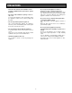
PREFACE ................................................................................................................................................................................ 2 FEATURES .............................................................................................................................................................................. 2 PRECAUTIONS ...............................................................................................................................
PREFACE The WJ-SX350 Matrix Switcher allows for flexible control of thirty two (32) cameras and eight (8) monitors. Tour and Group sequences for customized security requirements can be easily established through the user-friendly, on-screen menu setups. FEATURES The WJ-SX350 Matrix Switcher enables control of the following functions: • Routing of up to thirty-two (32) cameras to any one of eight (8) monitors.
PRECAUTIONS • Do not expose the appliance to water or moisture, nor try to operate it in wet areas. Do take immediate action if the appliance becomes wet. Turn the power off and refer servicing to qualified service personnel. Moisture may damage the appliance and also cause electric shock. • Refer all work related to the installation of this product to qualified service personnel or system installers. • Do not block the ventilation opening or slots on the cover.
HOW TO USE THIS MANUAL The purpose of this manual is to provide step-by-step instructions for setting up and operating a Matrix Switcher System. If a Matrix Switcher is new to you, it is highly recommended that you read through this manual. If you are already familiar with the Matrix Switcher, you may skip Sections 1 and 2 and start from Section 3, Installations and System Connections. The contents of each section of this manual are summarized below.
SECTION 1 FEATURES OF THE MATRIX SWITCHER -5-
FEATURES OF THE MATRIX SWITCHER Shown below is an example of a basic system of the WJ-SX350 Matrix Switcher.
General Procedures 1. Select the desired monitor. (Monitor and Switcher are linked.) 2. Select the desired camera (Camera and Switcher are linked.) 3. The picture of the selected camera view is displayed on the selected monitor. 1. Log-in To operate the Matrix Switcher System, a registered operator must first supply his/her Operator Number and Password to the system.
Note: The desired camera selection may not be available due to one of the following reasons: 1. The operator is not allowed access to the desired camera because the Operator Registration has limited the operator's access to certain cameras. At this time PROHIBITED Indicator light up. See page 11 for more details. 2. The desired camera is currently selected by another operator who has a higher operator priority, and therefore, control over that camera. In this case, the BUSY Indicator lights up. 4-4.
• DWELL Time The amount of time for each camera view is displayed on the monitor (Dwell Time) can be set from one (1) second to thirty (30) seconds in 1-second increments. This function is set from programming the Setup Menu. External Timing, which is controlled from the Time Lapse VTR, can also be selected from programming the Setup Menu.
2. Interface Alarm This alarm signal is supplied from the Alarm Input Connector (ALARM IN) on the rear of the Switcher. Up to thirty-two (32) alarm inputs are available. 7. Timer The timer function is used to programme and automatically activate Tour or Group Sequences according to the time of day and day of the week. There are sixteen (16) timers available in one day. 3. Video Input Signal Loss Alarm This alarm is indicated that camera signal loss has occurred. 8. Alarm 4.
Alarm Mode 3: Any alarmed pictures are assigned to any monitors. Mode 3 is a fully programmable mode. Any alarm can be shown on any monitor, plus sequence routines, presets and auxiliary relays in receivers can be activated. ANY Alarm 1 2 3 4 5 6 7 8 W Z X Y 8-3. Alarm Recall The WJ-SX350 Matrix Switcher can store up to ninety-nine (99) Alarm Events in its memory. The alarms may be recalled and displayed in chronological order on any desired monitor. 9.
9-1. Level Setting 10. Camera Title Operator access to various setup functions and system operations is determined by the operator's level. There are three (3) separate levels available (Level 1 is the highest). Camera titles are available for each camera input. Each title is composed of fifteen (15) characters per line, times two (2) lines. 9-2.
This table shows the system status in real time. Possible Active modes, as indicated in this table, are defined below. 13.
1 1 4 2 2 5 3 3 6 4 4 5 7 5 Operator's Priority 6 Operator's Partitioning 8 7 8 Priority 1 Operator 1 Controller 1 POWER LOCK ALARM MONITOR CAMERA BUSY PROHIBITED Priority 2 Operator 2 Controller 2 POWER LOCK ALARM MONITOR CAMERA CAMERA SITE CONTROL BUSY PROHIBITED POWER 4 5 6 7 8 1 2 3 CAMERA BUSY PROHIBITED CAMERA SITE CONTROL IRIS 4 5 6 DOWN UP 0 FOCUS 7 8 2 3 4 5 6 WIDE 9 FAR NEAR R L ZOOM TELE 1 R L WIDE 9 OPEN CLOSE FAR NEAR R
SECTION 2 DETAILED PRODUCT DESCRIPTION -15-
MAJOR OPERATING CONTROLS AND THEIR FUNCTIONS ALARM LOGIN ALARM SEQUENCE CAMERA SITE CONTROL ALT BACK FWD SEQ PAUSE SEQ 1 2 3 4 5 6 7 8 9 MON 0 CAM IRIS SHIFT FUNCTION ALL RESET −1 CAM DEC +1 CAM INC PRESET POSI RECALL BUSY OPEN IRIS RESET ACK/RESET OPERATE AUTO FOCUS CLOSE CAM PROHIBITED STATUS MENU SET UP ESC SET BACK FWD CAM POSI HISTORY AUTO PAN RANDM PAN ON UP FOCUS OFF NEAR FAR LEFT AUX 1 WIPER RIGHT ZOOM TELE WIDE DOWN AUX 2 DEF 350 MATRIX
9. Increment button (+1CAM INC) This button is used to move a sequence one step forward from the step that was previously paused on the selected monitor by pressing the PAUSE button. Also, when the selected monitor is in the spot mode, pressing this button will replace the selected camera with the next higher camera number. 18.
28. History Back button (HISTORY BACK) This button is used to display the previous camera picture on the selected monitor. Each operation of this button backs up the camera picture by ones. This button also selects the previous page or step of the setup tables on the SETUP MENU. 32. Prohibited LED indicator (PROHIBITED) This indicator lights up for two seconds when the incorrect operator number or password is selected to Log-in.
41. Camera Output Connector (CAMERA OUT) The video signal connected to the Camera Input Connector (CAMERA IN) is looped through to this connector with an automatic 75Ω termination. Designation Pin Number 1 2 3 4 5 6 7 8 9 10 11 12 13 14 15 16 17 18 19 20 21 22 23 24 25 42. Camera Input Connector (CAMERA IN) This connector accepts either a colour or B/W composite video signal from a camera. 43.
-20-
SECTION 3 INSTALLATION AND SYSTEM CONNECTIONS -21-
INSTALLATIONS The installations described below should be performed by qualified service personnel or system installers. 4. Remove the two screws shown below from the rear of the Matrix Switcher. Then carefully pull the printed circuit board toward the rear until the switches shown below become visible. ■ DIP Switch Setting ● Alarm Reset Output Setting Caution: Before disassembling the Matrix Switcher, be sure to turn off the Power Switch of the Matrix Switcher. 1.
● Mounting in the Rack Note: Be sure to confirm the switch number before setting, as these switches are not arranged in numerical order on the board. The switch arrangement on the board, from right to left, is as follows: SW7 (Reset Out 1), SW9 (Reset Out 3), SW8 (Reset Out 2), SW10(Reset Out 4), SW11 (Reset Out 5), SW13 (Reset Out7), SW12 (Reset Out 6), and SW14(Reset Out 8). 1. Remove the four rubber feet by removing the four screws from the bottom of the Matrix Switcher. 6.
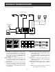
SYSTEM CONNECTIONS An example of the basic system connection is shown below.
■ Connection with the Camera Sites Connect the Camera Site equipment to the Camera Input Connectors (CAMERA IN 1-32) on the rear of the Matrix Switcher. Connect the Camera Site equipment to the RS485 Terminal on the rear of the Matrix Switcher, when specified equipment is connected. Note: If you use cables assembled from locally procured materials, it is important that only high quality, data grade cable, suitable for RS-485 “2-wire twisted pair shielded cable” is used.
■ Connection with the Time Lapse VTR Connect the Time Lapse VTR as shown in the example below.
SECTION 4 SOFTWARE SETUP -27-
SETUP MENU The SETUP MENU provides a way of controlling functions that are not accessible by a direct operation. Access to the SETUP MENU is limited to operators with the proper operator's level. The following buttons and switches are valid in the SETUP MENU: Joystick Controller: Moves the cursor to the desired item on the menu or table. CAM (SET) button: Executes the setting or selection. MON (ESC) button: Escapes from the programming mode or menu. Numeric buttons: Enter any numerical input.
■ SETUP MENU As shown below, the SETUP MENU has seven main sub menus: Program, Operator, System, Camera Data Load, Camera Title, Camera Position Map and Function Key. Four of these, Program, Operator, System and Camera Data Load, are further divided into additional sub menus.
The SETUP MENU allows access to seven main items by On-Screen selection as shown below. SETUP P O S C C C F R P Y A A A U O E S M M M N GRA RAT TEM DA ERA –PO CTI 1. T-SEQ MENU (Tour Sequence) This table is used to programme or edit a Tour Sequence. There are thirty-two (32) Tour Sequences available, each with thirty-two (32) steps. Each step consists of a camera number (CAM), an associated Pan/Tilt preset position or auxiliary switches [ PRE(AUX) ], and a dwell time (DWELL).
To initialize the edited sequence 012345678901234567890123 T – S E Q N O. 0 1 ( S T E P = 2 5 – 3 2 ) < C P D < C P D < A R W < A R W S M E EL S M E EL TEP = (AUX) L TEP = (AUX) L 2 2 0 0 2 2 – 0 5 5 1 3 9 9 – 3 2 2 – 0 3 3 0 0 6 6 – 2 0 0 2 2 2 2 0 0 3 3 0 0 7 7 2 1 1 1 5 1 2 2 – 0 3 3 – 0 Note: Once a sequence has been initialized, the previous sequence data cannot be restored. 8>> 8 – 5 2>> 2 – 5 T–SEQ S E Q N O. AUTO SKIP =01 =OFF P R O G. C L E A R = N O 3.
Or select the Auxiliary Switch Mode shown below by pressing the +1CAM INC or –1CAM DEC button. To programme or edit a Group Sequence, do the following: Parameter 1N: 1F: 2N: 2F: Caution: Before programming or editing a Group Sequence, the Alarm Mode must be in the OFF mode first. Follow Alarm Mode Setting Procedures on page 34. 1. Move the cursor to the SEQ NO. parameter by moving the Joystick Controller. 2. 6.
3. Move the cursor to position 1, 2, 3 and 4 by moving the Joystick Controller. Enter the desired hours (military time) and minutes by pressing the Numeric buttons. 3. TIMER EVENT This table is used to enable and disable Tour and Group Sequences according to the time of day and day of the week. There are sixteen (16) events available in one day. 4. When satisfied with the programming of timers on this page, press the HISTORY FWD button to select the next page.
11. Repeat the above procedures to programme other days. 4. ALARM EVENT Select ALARM EVENT from the PROGRAM MENU, then press the CAM (SET) button. The ALARM EVENT menu appears on the monitor. Cautions: • When programming a timer event that extends into the next day, divide the timer event into two separate events and programme both events separately.
1. Move the cursor to the ALARM MODE parameter by moving the Joystick Controller, then select the desired alarm mode by pressing the +1CAM INC or –1CAM DEC button. 1. Move the cursor to the DWELL parameter by moving the Joystick Controller, then select the desired Dwell Time (1-30) by pressing the Numeric buttons or the +1CAM INC or –1CAM DEC button. 2.
4. Move the cursor to the PRE parameter by moving the Joystick Controller, then enter a Preset Position Number, if applicable, by pressing the Numeric buttons or the +1CAM INC or –1CAM DEC button. Then press the CAM (SET) button to display the mode setup table of the selected alarm input as shown below. ALARM MODE 5. Move the cursor to the DWELL parameter by moving the Joystick Controller, then enter the desired Dwell Time(1-30) by pressing the Numeric buttons or the +1CAM INC or –1CAM DEC button.
2. Select a desired day by pressing the +1CAM INC or –1CAM DEC button. Then press the CAM (SET) button to execute the selection. The selected alarm schedule menu appears on the monitor as shown below. • Group Sequence Mode 1. If the GROUP is selected on the above menu, the display will change as follows: ALARM q MODE3(AL=01) MODE =GROUP S E Q N O. = 0 2 << M1 S << M5 G M2 S M6 G M3 T M7 G M4 T M8 G >> >> 2. Move the cursor to the SEQ NO.
■ OPERATOR 1. LEVEL TABLE The OPERATOR menu allows access to two items: the level table and operator registration. This table is used to determine what setup functions and operations may be performed by the three (3) operator levels. There is a total of nineteen (19) functions or operation items available through the three (3) pages of tables. Select OPERATOR on the SETUP MENU by pressing the Joystick Controller, then press the CAM (SET) button to display the OPERATOR menu as shown below.
2. REGISTRATION (Operator Registration) Cautions: • To prevent unauthorized access, be sure to change the Password preset at the factory. • If an operator's level for access to the item “SETUP MENU” or “OPERATOR” on the LEVEL TABLE has not been registered, that operator will not be allowed access to the SETUP MENU a second time. This table is used to establish operator numbers for the users of the system along with associated passwords, operator levels and priorities.
■ SYSTEM 1. Move the cursor to the desired controller and monitor parameter by moving the Joystick Controller, then select OK or NG by pressing the +1CAM INC or –1CAM DEC button. As shown below, the SYSTEM menu allows access to eight items. P: •: Select SYSTEM on the SETUP MENU by moving the Joystick Controller, then press the CAM (SET) button to display the SYSTEM menu as shown below. 2.
3. PC COM. (PC Communication) 4. CAM PORT SELECT (Camera Port Select) This table is used to set the Communication Parameters between the Personal Computer and the Matrix Switcher. This table is used to select either RS485 port 1 or 2 for the cameras. Up to sixteen (16) cameras can be assingned to each port. Select PC COM. on the SYSTEM menu by moving the Joystick Controller, then press the CAM (SET) button to display the PC COM. menu as shown below.
5. RS485 CAM COM. (RS485 Camera Site Communication) 6. EXT TIMING (External Timing) This table permits the sequence dwell time on the selected monitor to be synchronized with the time lapse mode set in the associated Time Lapse VTR. This table is used to set the Communication Parameters between the RS485 Port installed in the Matrix Switcher and the Camera Site.
7. CLOCK SET 8. RESET This table is used to set the present time and date. This table is used to reset the system to the initial factory settings. Note that this function clears all data setup previously, so avoid using it unless necessary. This table can also be used to clear stored alarm records. Move the cursor to CLOCK SET on the SYSTEM menu by moving the Joystick Controller, then press the CAM (SET) button to display the CLOCK SET menu as shown below. CLOCK DD 1 . . MMM JAN . .
■ DATA LOAD 2. DOWN LOAD MODE Move the cursor to CAM DATA LOAD on the SETUP MENU by moving the Joystick Controller, then press the CAM (SET) button to display the DATA LOAD menu as shown below. This table is used to save the camera setup data into the memory of the Matrix Switcher. If the setup content of the camera is lost due to malfunctioning or replacement of a camera, you can simply reload the data stored in the Matrix Switcher.
6. If SELECT MODE is selected, the following menu appears on the monitor. 3. UP LOAD MODE This table is used to upload camera setup data from the Matrix Switcher’s memory to each camera. D O W N L O A D S E L.
6. If SELECT MODE is selected, the following menu appears on the monitor. C01 C02 C03 C04 C05 C06 C07 C08 C0 U P L O A D S E L. • C09 • C17 • C10 • C18 • C11 • C19 • C12 • C20 • C13 • C21 • C14 • C22 • C15 • C23 • C16 • C24 1 LOADING STA MO • • • • • • • • RT DE C 25 C 26 C 27 C 28 C29 C 30 C 31 C 32 11. Press the MON (ESC) button to return to the original camera view. • • • • • • • • ■ CAMERA TITLE This table is used to edit the camera titles to be displayed on the monitor screen.
1. Move the cursor to the PAGE COUNT parameter by moving the Joystick Controller, then select the desired page number by pressing the Numeric buttons or the +1CAM INC or –1CAM DEC button. (In the initial state, it is not necessary to select the page number.) Press the CAM (SET) button to display the editing table as shown below. 3. Repeat the above procedure until the title for a selected camera is completed. 4.
■ FUNCTION KEY MODE This table is used to programme and edit the camera functions by assigning a 1-digit number to each function. The function can then be called up by simply pressing the respective Numeric button. Note: This function requires the use of a camera that is equipped with the necessary features. Move the cursor to FUNCTION KEY on the SETUP MENU by moving the Joystick Controller, then press the CAM (SET) button to display the FUNCTION KEY MODE menu as shown below.
SECTION 5 OPERATING PROCEDURES -49-
OPERATING PROCEDURES Before starting the following procedures, all system components should be turned on. Note: The BUSY indicator blinks when another operator, with a higher operator priority, is currently controlling the monitor outputs. The lower priority operator may not log-in while this indicator is blinking. 1. Log-in • Auto Login Setting 1. Turn on the power switches of all system components. AUTO LOGIN is set to On mode, any operator can log-in as any operators previously.
2. Press the Focus (FOCUS NEAR/FAR) switch to adjust the lens focus to achieve a sharply focused picture while observing the monitor. 3. Camera Selection 1. Select the camera number (1 to 32) by pressing the Numeric buttons, then press the CAM (SET) button. The selected camera picture appears on the currently selected monitor. FOCUS NEAR 1 2 3 4 5 6 7 8 9 MON 0 CAM ESC SET BACK FWD FAR 3.
5. Pan/Tilt Control Note: To be able to use the above function, the Preset Position Number must have been set with that camera. Refer to the camera’s operating instructions for setting procedures. 5-1. Pan/Tilt Control (Manual Operation) 1. Select the desired monitor and camera. Refer to Monitor Selection and Camera Selection on pages 50 and 51. 5-3. Pan/Tilt Control (Home Position Operation) 2. Move the Joystick Controller to move the Pan/Tilt Head towards the desired direction.
1 2 3 4 5 6 7 8 9 MON 0 CAM ESC 1. Select the desired monitor and camera. Refer to Monitor Selection and Camera Selection on pages 50 and 51. CAM POSI 2. Press the AUTO PAN/RANDM PAN ON button, while SHIFT is in Off position (Indicator light off), to activate Auto Panning function. To cancel Auto Panning, press the AUTO PAN/RANDM PAN OFF button while SHIFT is in Off position (Indicator light off).
SHIFT ON OFF AUX 1 1 2 3 4 5 6 7 8 9 MON 0 CAM ESC SET BACK FWD HISTORY WIPER Caution: To prevent premature wearing of the wiper blades, be sure to turn off the wiper when it is not needed or before selecting another camera for viewing. 3. Press the FWD SEQ button to run the sequence in forward direction, or press the BACK SEQ button to run the sequence in reverse direction. SEQUENCE 6-2. Defroster Control BACK FWD SEQ PAUSE SEQ 1. Select the desired monitor and camera.
6. Press the BACK SEQ button to continue a sequence that was previously paused by the PAUSE button. The sequence will continue in the reverse direction from the step that was previously paused by the PAUSE button. 7-2. Group Sequence The following function is available only if a Group Sequence has been previously established through the Setup Menu. As described on page 31, up to four (4) Group sequences can be set up. 7.
9. Camera Function Control 1 2 3 4 5 6 7 8 9 MON 0 CAM ESC SET BACK FWD The camera functions (Electronic Shutter, Electronic Sensitivity Up, ALC/MANUAL, AGC, White Balance, BLC, Site Alarm, Camera Power, Camera Preset Sequence, Refresh Position) can be remote controlled on the Switcher’s front panel. Control operation should be performed with the monitoring camera picture on the selected monitor.
9-2. Electronic Sensitivity Up Mode 9-5. White Balance Mode 1. Select the desired monitor and camera number Refer to Monitor Selection and Camera Selection on pages 50 and 51. 1. Select the desired monitor and camera. Refer to Monitor Selection and Camera Selection on pages 50 and 51. 2. Select 4 by pressing the Numeric button, then press the FUNCTION button to toggle the camera’s Electronic Sensitivity between Up AUTO, FIX and OFF. 2.
9-10. Camera Preset Sequence Mode 10. Camera Setup Note: The following function requires the use of a camera with preset panning capability, such as the Panasonic WV-CSR600 series. The following functions are available with cameras that have setup functions. 1. Select the desired monitor and camera. Refer to Monitor Selection and Camera Selection on pages 50 and 51. The three panning modes shown below are available. AUTO PAN mode: The camera automatically turns within the preset panning range.
6. To escape from the Setup Menu, press the ALT button. The indicator on the button lights up. Then press the CAM MENU button. BACK FWD HISTORY 3. Press the HISTORY FWD button repeatedly to forward the picture by ones. Note: When the latest (or oldest) picture is displayed on the selected monitor, pressing the HISTORY FWD or HISTORY BACK button will not replace the currently selected picture on the monitor. 11.
1. Press the ALT button. The LED indicator on the button lights up. 2. Press the ACK/RESET button once for alarm acknowledgement. The LED indicator on the button blinks rapidly. 2. Press the ACK/RESET button to suspend activation of the alarm. The LED indicator on the button lights up. 3. Press the ACK/RESET button once again for alarm reset. The LED indicator light goes off. ALT ACK/RESET 3. To cancel this function, press the ALT button, then press the ACK/RESET button.
15. Camera Site Status Display 16. System Status Display To display the Camera Site Status Table, follow the procedures below. Following is the procedure to display the System Status Table. This table shows the system status in real time. 1. Select the desired monitor and a camera to display the status. Refer to Monitor Selection and Camera Selection on pages 50 and 51. 1. Select a monitor to display the System Status Table. Refer to Monitor Selection on page 50. 2. Press the ALT button.
17. Priority Lock 18. Log-out This function is used to retain control of a monitor for an operator, even after that operator has selected another monitor or has logged out. This function is used when an operator is leaving the Switcher, or no longer requires access to the system. 1. Select 00 by pressing the Numeric buttons, then press the FUNCTION button to log out. Caution: This function will prevent operators with a lower priority from gaining control of a monitor.
SECTION 6 SPECIFICATIONS -63-
SPECIFICATIONS General Power Supply: Power Consumption: Max. Number of Camera Inputs: Max. Number of Monitor Outputs: Max. Number of Alarm Inputs: Max. Number of Alarm Outputs: Max.
Setup Menu Camera Switching Dwell Time: Max. Number of Sequences: Number of Programming Steps: Timer Event Program Timer Events (Start & Stop): Formats of Timer Event Program: Alarm Program Max. Number of Alarm Recalls: Alarm Activations: Timer Alarms (Start & Stop): Formats of Timer Alarm Program: Operator Setup Max. Operator Registrations: Access Operator Levels: Min. 1 s to max.
Matsushita Electric Industrial Co., Ltd. Central P.O.