
Installation Guide

19
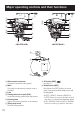
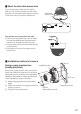
1 Connect the ∅3.5 mm miniature plug (mono channel) to the adjustment monitor
output jack.
Important:
• This video output is intended for confirmation of view angle, etc. during installation or repair
service, and not for recording or monitoring.
Note:
• Adjustment monitor output jack is prior to video output cable. Video cannot be output through
the video output cable after connecting the adjustment monitor.
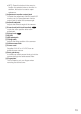
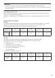
2 When the camera is installed on the wall, select "ON" for "UPSIDE-DOWN" in the setup
menu. (Refer to page 23 of Operating Instructions for detailed information)
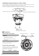
3 Pan, tilt and azimuth adjustment
Important:
• When adjusting pan, tilt or azimuth, do not hold the lens of the camera.
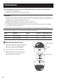
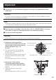
1 Adjustment of panning position
Loosen the panning table lock screw and
rotate the table to determine the panning
position (adjustable range: -170 °
to +180 °).
• The panning position can be adjusted
between +180 ° (clockwise) and –170 °
(counter-clockwise).
• After the panning position is determined, fix
the panning table with the panning table
lock screw.
(Recommended torque: 0.39 N·m {0.29 lbf·ft})
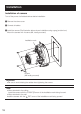
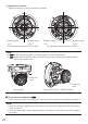
2 Adjustment of tilting position
Turn the tilting table to adjust the tilting
position of the camera. (adjustable range:
0 to 75 °)
• Tighten the tilting lock screw after
adjustment.
(Recommended torque: 0.59 N·m {0.44 lbf·ft})
Adjustment
Panning table lock
screw [LOCK]
Panning table
Original
position mark
Clockwise: 180 °
Counter-clockwise: 170 °
Adjustable range: 0 to 75 °