Operating Instructions ENGLISH System Controller WV-CU161 DEUTSCH Model No.
ENGLISH VERSION We declare under our sole responsibility that the product to which this declaration relates is in conformity with the standards or other normative documents following the provisions of Directives EEC/73/23 and EEC/89/336. Vi erklærer os eneansvarlige for, at dette produkt, som denne deklaration omhandler, er i overensstemmelse med standarder eller andre normative dokumenter i følge bestemmelserne i direktivene 73/23/EEC og 89/336/EEC.
PREFACE ..................................................................................................................................................................................... FEATURES ................................................................................................................................................................................... PRECAUTIONS .........................................................................................................................
PREFACE The WV-CU161 System Controller is designed for one-to-one use with the Combination Camera such as the WV-CS850 series Combination Camera or the WV-RC100/WV-RC150 Receiver. Camera control is performed by multiplexing the control signal with the video signal by connecting an AV Codec or the like, or via RS-485 site communication*1. Alarm signals, such as motion detector signals, can be supplied to external equipment from a built-in alarm output connector.
PRECAUTIONS • Refer all work related to the installation of this product to qualified service personnel or system installers. • Do not block the ventilation opening or slots on the cover. To prevent the appliance temperature from rising, place the appliance at least 5 cm (2 inches) away from the wall. • Do not drop metallic parts through slots. This could permanently damage the appliance. Turn the power off immediately and refer servicing to qualified service personnel.
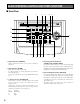
MAJOR OPERATING CONTROLS AND THEIR FUNCTIONS ■ Front View q w OPERATE ALARM u y r t System Controller WV-CU !3 1 SHIFT 2 3 !4 SUSPEND !5 B/W PATROL STOP ALARM RESET 4 5 6 7 8 9 DEF AUX1 AUX2 L R e FOCUS AUTO FOCUS HOME SLOW CAMERA FUNCTION FAR NEAR PROGRAM !6 UP PATROL LEARN WIPER CAMERA SETUP SETUP PATROL PLAY AUTO PRESET WIDE ESC TELE DOWN ZOOM 0 CLOSE SET IRIS OPEN IRIS RESET PROGRAM PRESET !2 !0 q Operate Indicator (OPERATE) Lights up while the powe
y Auto Panning/Black and White Selection/Patrol Stop Button (AUTO/B/W/PATROL STOP) AUTO: Pressing this button will activate the auto panning function of cameras provided with this feature. B/W: Pressing this after pressing the SHIFT button will display the picture in black and white on the monitor. PATROL STOP: Pressing this button while holding down the CAMERA SETUP/SETUP/PROGRAM button will stop to program the camera patrol learning function.
■ Rear View e ALARM RS485 ALARM IN ALARM OUT RECOVER IN RESET OUT T R G B A B A 4 3G2 1 DATA VIDEO OUT TERM LINE ON 4 COAX OFF 2 RS485 CAMERA IN POWER OFF ON SIGNAL GND ALARM IN y t r q u w q Alarm Input Terminal (ALARM IN) Accepts the alarm signals from external devices such as alarm sensor when the alarm switch y is in the upper position. w Alarm Output Terminal (ALARM OUT) The alarm output signal is provided at this terminal for the Time Lapse VTR etc.
SETUP The WV-CU161 can be programmed by setting switches or from the interactive Setup menu as described below. 1. DIP Switch Setting (See page 10.) 2. Data Switch Setting For setting the mode of communication between the WV-CU161 and the combination camera. 3. Alarm Switch Setting For setting up the alarm terminal. Turn off the power before setting this switch. 4. Setup of WV-CU161 Display the Setup menu (see page 17) to setup the WV-CU161.
CONNECTIONS Check the DIP switch settings before connecting this controller. They need to be changed only if you want to change the system settings. The following setting procedure should be made by qualified service personnel or system installers. ■ DIP Switch Setting Caution: Unplug the AC cord before changing any DIP switch setting. ● Removing the Bottom Cover for SW1 Remove two screws. 1. Take off the bottom cover by removing the two screws.
SYSTEM CONNECTION The WV-CU161 can be connected with a camera, a video monitor and a Time Lapse VTR. A typical connection example is shown below.
■ Connection with a Video Switcher Connected with a video switcher, the WV-CU161 allows you to control multiple combination cameras.
■ RS-485 Site Communication Connection via Codec for Camera Distance of 1 200 m (4 000 ft) or More RS-485 Cable Coaxial Cable DATA PORT WV-CS850 series AV Codec Public lines AV Codec VIDEO OUT DATA PORT System Controller WV-CU OPERATE ALARM 1 2 3 SUSPEND 4 5 6 CAMERA SETUP SERUP 7 8 9 SHIFT CAMERA IN PATROL PAY AUTO B/W UP ALARM RESET WIPER DEF AUX1 AUX2 NEAR RESET CAMERA FUNCTION FAR R L FOCUS AUTO FOCUS PROGRAM HOME PRESET WIDE SET CLOSS 0 ESC TELE IRIS DOWN OPEN
■ Connection with a Time Lapse VTR Connect the time lapse VTR as shown in the example below. Make sure the polarity of the buzzer matches the terminal. Connect the positive (+) terminal of the buzzer to the Alarm Output Terminal. The Alarm Output Terminal is an Open Collector terminal with a capacity of 16 V DC, 100 mA or less. (1) Connect the buzzer as shown below if its rating lies within the capacity of the Alarm Output Terminal.
■ RS-485 Terminal Control data is transmitted and received to and from other peripherals. Use a data grade, double-shielded, twisted pair cable, suitable for the RS-485. Cable length may be extended up to 1 200 m (4 000 ft).
SETUP MENU The Setup menu has four main submenus: Alarm Setup, System Setup, Preset Data Load, and Communication. All of these main menus are further divided into submenus. SETUP MENU ALARM SETUP*1 ALARM TERMINAL SYSTEM SETUP*2 PRESET DATA LOAD*3 PRESET DATA LOAD CAM 1 PRESET DATA LOAD CAM 2 PRESET DATA LOAD CAM 3 PRESET DATA LOAD CAM 4 PRESET DATA LOAD CAM 5 PRESET DATA LOAD CAM 6 PRESET DATA LOAD CAM 7 PRESET DATA LOAD CAM 8 COMMUNICATION*4 *1 To set the alarm operation mode when an alarm is activated.
■ Displaying the Setup Menu 1. Check that the camera, the monitor and peripherals are connected correctly and securely. 2. Switch all the system components on. The operate indicator of the WV-CU161 lights up. The picture of the camera appears on the monitor. 3. Press the SHIFT button, and then press the CAMERA SETUP/SETUP/PROGRAM button for 2 seconds or more. 4. The SETUP MENU appears. • Joystick Controller L R Up: To select modes. R Down: To select modes. R Left: To decrease the parameter.
• For using alarm input terminals 1-4 ALARM SETUP ALARM DISPLAY ON SITE ALARM ON TERM.ALARM ON ALARM OUTPUT 10S ALARM BUZZER ON ALARM TERMINAL (1) Alarm Display Setting This item lets you select whether or not the message ALARM on the monitor when the alarm is activated. 1. Display the ALARM SETUP menu. 2. Select ALARM DISPLAY by moving the joystick up or down. 3. To have ALARM displayed, select ON for the ALARM DISPLAY parameter. Otherwise select OFF by moving the joystick to the right or left.
• For using alarm input terminals 1-4 ALARM SETUP ALARM DISPLAY ON SITE ALARM ON TERM.ALARM ON ALARM OUTPUT 10S ALARM BUZZER ON ALARM TERMINAL ■ System Setup 1. Display the Setup menu. 2. Select SYSTEM SETUP by moving the joystick up or down. 3. Press the PRESET/SET/PROGRAM PRESET button. The SYSTEM SETUP menu appears on the monitor as shown below. SYSTEM SETUP 1. Display the ALARM SETUP menu. 2. Select ALARM TERMINAL by moving the joystick up or down. 3. Press the PRESET/SET/PROGRAM PRESET button.
■ Preset Data Load Setting 1. Display the Setup menu. 2. Select PRESET DATA LOAD by moving the joystick up or down. 3. Press the PRESET/SET/PROGRAM PRESET button. The PRESET DATA LOAD screen appears on the monitor as shown below. PRESET DATA LOAD CAM1: CAM2: CAM3: CAM4: CAM5: CAM6: CAM7: CAM8: P : Data saved. ■ : No Data saved. (The factory default setting for all cameras from CAM1 to CAM8 is ■.) (1) Download Setting 1. Display the PRESET DATA LOAD menu. 2.
(2) Upload Setting 1. Display the PRESET DATA LOAD menu. 2. Select a camera number between CAM1 and CAM8 by moving the joystick up or down. 3. Press the PRESET/SET/PROGRAM PRESET button. The camera number and upload menu appear on the monitor as shown below. • In case of RS-485 Site Communication mode, check that the unit address is the same as set on the combination camera. If the numbers do not agree, the camera cannot be operated. Therefore, preset data cannot be uploaded.
7. After setting all data titles, press the HOME/ESC button to return to the Preset Data Menu. To replace a specific character 1. Move the cursor to the title area by moving the joystick. 2. Move the cursor on the character to be replaced by moving the joystick to the right or left. 3. Move the cursor from there to the desired character in the character area by moving the joystick up or down, and move the cursor to the desired character by moving the joystick up, down, right, or left. 4.
(4) Parity Check Setting This item lets you set the parity bit for RS-485 communication. 1. Display the COMMUNICATION menu. 2. Select PARITY CHECK by moving the joystick up or down. 3. Select NONE, EVEN or ODD for parity check by moving the joystick to the right or left. The initial factory setting is NONE. Note: This setting must be compatible with the peripherals connected. (5) Stop Bit Setting This item lets you set the number of stop bits for RS-485 communication. 1. Display the COMMUNICATION menu. 2.
OPERATING PROCEDURES CAMERA CONTROL FUNCTIONS It is necessary to setup the camera before using the camera control functions. For further information, refer to the Operating Instructions for the respective combination camera (See page 30). You can also set it up from Camera Setup menu if you operate a system. ■ Lens Control The following functions are available with cameras provided with controllable lens. 1. Press the FOCUS NEAR or FOCUS FAR button to adjust the lens focus while watching the monitor.
■ Operation of Combination Camera ● Auto Pan It is necessary to setup the combination camera before operating it. For further setup information, refer to the Operating Instructions for the combination camera (See page 30). You can also set it up from the Camera Setup menu if you operate a system. The following functions are available only with cameras provided with the pan/tilt head specified for this operation. It is necessary to program the auto pan function for the combination camera beforehand. 1.
● Camera Patrol Function The following function is available with combination cameras provided with the camera patrol function. The camera patrol function enables the combination camera to learn joystick movements and zooming operation. To program the camera patrol learning function, see page 31. 1. Press the PATROL PLAY/PATROL LEARN button to move the combination camera according to the data saved in the memory.
2. Press the SLOW/CAMERA FUNCTION button after pressing the SHIFT button. SLOW • Electronic Sensitivity Enhancement The following function is available only with cameras provided with the electronic sensitivity function. 1. Press numeric buttons 1, 7 and 7. CAMERA FUNCTION SHIFT 3. To cancel the electronic shutter function, press numeric buttons 1, 7 and 2. 1 2 3 4 5 6 7 8 9 HOME 4. To increase electronic shutter speed, press numeric buttons 1, 7 and 3. PRESET 0 ESC SET PROGRAM PRESET 5.
■ Camera Housing Control ■ External Device Control ● Wiper Control ● Auxiliary Control The following function is available only with the cameras whose housing is provided with the wiper control function. The following function is available only in cases where external devices are connected to the receiver or the camera. 1. Press the WIPER/AUX1 button to operate the wiper on the selected camera. WIPER 1.
ALARM CONTROL FUNCTIONS ■ Alarm Reset When the WV-CU161 receives an alarm signal from a camera site, an alarm is activated. The WV-CU161 can handle the following alarms. Manual or Automatic resetting can be selected. When the alarm is reset, [ALARM] disappears from the monitor screen and the alarm reset signal is output from the alarm terminal on the rear panel. ● Camera Site Alarm Coaxial Multiplex Communication: Alarm is multiplexed with video signals from the camera.
CAMERA SETUP You can use the WV-CU161 to setup the camera from the Camera Setup menu. For further information, refer to the Operating Instructions for the individual combination cameras. Notes: • To display the special menu, move the cursor to [SPECIAL] on the Setup menu, and press numeric buttons 4 and 6 simultaneously for 2 seconds or more. • To restore all defaults, move the cursor to [CAMERA RESET]* on the Setup menu, and press buttons 4, 5 and 6 simultaneously for 2 seconds or more. ● Camera Setup 1.
● Camera Patrol Learning for Camera Patrol Operation The camera patrol learning function can be setup either from the Camera Setup menu or while operating the camera. Follow the procedures below to setup the function for a connected combination camera. ● Preset Position Setting Preset positions can be programmed either from the Camera Setup menu or from the System Controller. The following functions are available with the respective functions. 1.
INSTALLATION The installation should be made by qualified service personnel or system installers according to the following instructions. ■ Mounting in the Rack Note: Keep the Power On/Off Switch turned off while making the following installations. 1. Remove the Connector Panel and Bottom Cover from the controller by removing the four screws. Remove Connector Panel 2. Mount the Connector Panel onto the bottom by using the two screws removed above. Bottom Cover 3.
ALL RESET The System Controller WV-CU161 can be reset to the default settings as follows: 3. When all LEDs light up for a few seconds and go off (except for the Operate Indicator), resetting is completed. 1. Turn off the Power Switch. 2. Turn on the Power Switch while pressing numeric buttons 2, 4 and 6 simultaneously. 1 2 3 4 5 6 7 8 9 HOME PRESET 0 ESC SET PROGRAM PRESET 33 Note: The downloaded data for the camera remains as it is.
SPECIFICATIONS Power Source: Power Consumption: Camera Input: Alarm Input: Alarm Recover Input: Video Output: Alarm Output: Alarm Reset Output: Data Input/Output: Lens Control: Pan/Tilt Control: Housing Control: Camera Control: Alarm: Ambient Operating Temperature: Ambient Operating Humidity: Dimensions: Weight: 220-240 V AC, 50 Hz 7W Composite Video Signal: 1 V[p-p]/75 Ω No-voltage contact No-voltage contact Composite Video Signal: 1 V[p-p]/75 Ω Open collector: 16 V DC, 100 mA max.
Matsushita Electric Industrial Co., Ltd. Central P.O. Box 288, Osaka 530-91, Japan N0400-1060 2000 © Matsushita Communication Industrial Co., Ltd. All rights reserved.