Operating Instructions Color CCTV Camera Model No. WV-CZ392E WV-CZ492E This illustration represents WV-CZ392E. Before attempting to connect or operate this product, please read these instructions carefully and save this manual for future use. The model number is abbreviated in some descriptions in this manual.
We declare under our sole responsibility that the product to which this declaration relates is in conformity with the standards or other normative documents following the provisions of Directives 2006/95/EC and 2004/108/EC. Vi deklarerar härmed vårt fulla ansvar för att den produkt till vilken denna deklaration hänvisar är i överensstämmelse med de standarder eller andra normativa dokument som framställs i direktiv nr 2006/95/EC och 2004/108/EC.
Contents Important safety instructions............................................................................................................. 4 Limitation of liability........................................................................................................................... 5 Disclaimer of warranty....................................................................................................................... 5 Preface..............................................................
Important safety instructions 1) Read these instructions. 2) Keep these instructions. 3) Heed all warnings. 4) Follow all instructions. 5) Do not use this apparatus near water. 6) Clean only with dry cloth. 7) Do not block any ventilation openings. Install in accordance with the manufacturer's instructions. 8) Do not install near any heat sources such as radiators, heat registers, stoves, or other apparatus (including amplifiers) that produce heat.
Limitation of liability THIS PUBLICATION IS PROVIDED "AS IS" WITHOUT WARRANTY OF ANY KIND, EITHER EXPRESS OR IMPLIED, INCLUDING BUT NOT LIMITED TO, THE IMPLIED WARRANTIES OF MERCHANTABILITY, FITNESS FOR ANY PARTICULAR PURPOSE, OR NON-INFRINGEMENT OF THE THIRD PARTY'S RIGHT. THIS PUBLICATION COULD INCLUDE TECHNICAL INACCURACIES OR TYPOGRAPHICAL ERRORS. CHANGES ARE ADDED TO THE INFORMATION HEREIN, AT ANY TIME, FOR THE IMPROVEMENTS OF THIS PUBLICATION AND/OR THE CORRESPONDING PRODUCT (S).
Preface This product is a 1/4 type CCD color CCTV camera. Connection of this product to a video monitor allows users to use this product as a monitoring camera. • WV-CZ392: 36x zoom • WV-CZ492: 36x zoom, Super Dynamic 6 About notations The following notations are used when describing the functions limited for specified models. The functions without the notations are supported by all models. CZ392 CZ492 The functions with this notation are available when using the model WV-CZ392.
Precautions The following points as well as the contents of "Warning" and "Caution" shall be observed. This product shall be installed in a vibration-free place. Refer installation work to the dealer. Failure to observe this may cause screws and bolts to be loosened and consequently to fall resulting in injury. Installation work requires technique and experiences. Otherwise injury, or damage to this product may result. Be sure to consult the dealer. Do not insert any foreign objects.
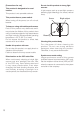
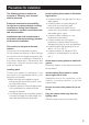
[Precautions for use] This product is designed to be used indoors. This product is not operable outdoors. This product has no power switch. When turning off the power, turn off a circuit breaker. Do not aim this product at strong light sources. A light source such as a spot light causes a blooming (light bleeding) or a smear (vertical lines).
Precautions for installation The following points as well as the contents of "Warning" and "Caution" shall be observed. Panasonic assumes no responsibility for injuries or property damage resulting from failures arising out of improper installation or operation inconsistent with this documentation. Installation work shall be performed in accordance with the technology standard of the electric installation. This product is designed to be used indoors. This product is not operable outdoors.
Radio interference When the camera is used near TV/radio antenna, strong electric field or magnetic field (near a motor or a transformer), images may be distorted and noise sound may be produced. In such a case, run the camera cable through specialized steel conduit tubes. Locally procure the screws Screws are not supplied with this product. Prepare the screws according to the material, structure, strength and other factors of the mounting area and the total weight of objects to be mounted.
Major operating controls 1 Tripod mount base 6 Lens control terminal 2 DC power terminal [12V IN] 3 Power indicator [POWER] 7 Alarm output terminal 4 Operation buttons 1 5 Video output connector 2 2 8 Day/Night input terminal [D/N IN] 9 RS485 data In/Output terminal 2 2 ! RS485 terminal select switch 1: Zoom, Focus and Auto Focus can be controlled by setting button if the setup menu is not opened. 2: For more information about 6 ~ 9, refer to page 14.
Installation and connection Important: • The following installing and connections should be made by qualified service personnel or system installers in accordance with all local codes. 1 Secure the camera mount bracket (option) to an installation position, and mount the camera on the camera mount bracket. Important: • The camera mount bracket shall be mounted on the foundation part of the construction or a part with adequate strength.
2 The video output cable (locally procured) is connected to the video output connector. Important: • Be sure to turn off the power of each device before connection. • Be sure tp secure the coaxial cable connectors. The maximum extensible length is shown in the table.
4 Connet the cable of control terminal to all control terminals. Control Terminals 1 2 3 4 5 NAME ZOOM (TELE: +, WIDE: -) FOCUS (NEAR: +, FAR: -) IRIS (OPEN: +, CLOSE: -) COM (For ZOOM, FOCUS, IRIS) ALARM 6 DAY/NIGHT 7 GND (For ALARM, DAY/NIGHT) 8 RS485 (B) 9 RS485 (A) I/O IN IN IN NOTICE TELE (+3 V - +15 V) WIDE (-3 V - -15 V) NEAR (+3 V - +15 V) FAR (-3 V - -15 V) OPEN (+3 V - +15 V) CLOSE (-3 V - -15 V) OUT Open collector-output max.16 V DC 100 mA OFF (OPEN)/ON (0 V) IN Pulled up to 5.
RS485 Data In/Output Terminal Control data is transmitted and received to and from other peripherals. For the farthest camera from RS485 convertor, set the RS485 terminal select switch to RS485 LINE TERM, or Hi-Z for other cameras. Switch Right Switch position Left Function Hi-Z Terminal resistor Note: T(B) 2 T(A)than AWG#22 (0.325 mm ) • Wire gauge size is thicker difference with the devices in long distance, communications • Because the existence of potential R(B) may be abnormal.
Cautions: • Check whether the stripped part of the wire is not exposed and is securely connected. • To prevent fire or electric shock hazard,use a UL listed cable (WV-1, style 1007) for the DC power terminal. • Do not mistake "+" and "-" when connecting the power cable to the DC power terminal of the camera. It may cause trouble. • This is not mobile equipment. Never feed the power from a battery source. 3 Tighten the screw of the power cord plug. 4 Connect the power cord plug to the DC power terminal.
Basic operation The description below explains how to operate the setup menu basically. The operations in the setup menu are performed with the operation buttons after calling up the setup menu on the connected video monitor. Screenshot 1 Step 1 Hold down the [SET] button for around 2 seconds to call up the top screen of the setup menu. Move the cursor to the item to be set, and press the [SET] button.
Setup menu Performing each setting item in the setup menu should be completed in advance to use this unit. Perform the settings for each item in accordance with the conditions of the camera shooting area. List of setup menu Setup item CAMERA CAMERA ID Description Performs the camera operation settings. This item specifies the camera title.
Screen transition diagram Quick setup (top) screen "CAMERA ID" screen WV-CZ392 CAMERA ID.
Screen transition diagram Advanced setup (top) screen CAMERA PRESET POSITION SPECIAL COMMUNICATION SCENE SELECT LANGUAGE QUICK SETUP PASSWORD LOCK OFF "CAMERA SETUP" screen **CAMERA SETUP** 1/2 CAMERA ID OFF ALC/MANUAL ALC SHUTTER AUTO AGC ON(MID) SENS UP OFF WHITE BAL ATW1 DNR LOW BW MODE AF MODE STOP AF VMD OFF **CAMERA ZOOM LIMIT STABILIZER PRIVACY ZONE UPSIDE-DOWN SETUP** 2/2 X36 OFF OFF OFF RET TOP "PRESET POSITION" screen **PRESET POSITION** PRESET MAP HOME POSITION OFF SELF RETURN OFF AUTO MODE
Advanced operation Quick setup menu Hold down the [SET] button for around 2 seconds to call up the camera setup menu. Following items can be set on the quick setup menu.
To enter a blank space in the camera ID (1) ALC Mode with BLC "ON" Move the cursor to "SPACE" and press the [SET] button. To erase all characters in the editing area 1. Press the [SET] button after selecting "ALC". The "ALC CONT" menu appears. **ACL CONT** BACK LIGHT COMP Move the cursor to "RESET" and press the [SET] button. All characters in the editing area disappear. To determine the display position of the camera ID 1. Move the cursor to "POSI", and press the [SET] button.
Loss of detail in dark areas Change to white Blinking 4. To cancel a masked area, move the cursor to the area, and press the [SET] button. To delete all the masking area, press the [RIGHT] and [LEFT] buttons at the same time for more than 2 seconds. 5. After masking is completed, press the [SET] button more than 2 seconds. 48 mask areas on the monitor screen disappear and the "ALC CONT" menu appears. (3) SUPER-D6 (Super Dynamic 6) CZ492 Note: 1.
• When the selected shutter speed caused flicker on condition that fluorescent lamps stay on, change this setting to "OFF". • When "MANUAL" is selected for "ALC/ MANUAL" and "FIX" is selected for "SENS UP", "AUTO" can be selected for "SHUTTER", but the AUTO function is not available. 4 Gain Control Setting Select "ON (LOW)", "ON (MID)", "ON (HIGH)" or "OFF".
• If white balance adjustment cannot be completed for some reason, "PUSH SET" will remain highlighted on the display. If this happens, it could mean that the color temperature is outside the supported range, or that illumination is too low. (3) For fine adjustment of the "AWC" press the [RIGHT] button, select "AWC ". The AWC fine adjustment menu appears on the monitor screen. Note: • When "AUTO" is selected, it is recommended to set "AGC" to "ON" before use.
BURST (BW) Setting Move the cursor to select "ON" or "OFF". ON: The burst signal is supplied along with the black-and-white composite video. OFF: The burst signal is not output. Default setting: ON Note: • With some monitors and VTR models, output of a camera images in the black-and-white mode will not display a proper image unless a burst signal is provided. Select "ON" for this setting when using equipment that requires a burst signal.
4. After masking areas, press the [SET] button more than 2 seconds. "MOTION DET" menu appears on the monitor screen. 5. Move the cursor to "ALARM", select "ON" or "OFF". ON: Turns on alarm output in the demo mode. OFF: Turns off alarm output in the demo mode. Default setting: OFF 6. Move the cursor to "DISPLAY MODE ", press the [SET] button to see the present setting. Demo Mode The demo mode divides the screen into 48 blocks and monitors changes in the luminance in each block.
" Zoom Limit Setting A limitation is provided to prohibit the ZOOM operation in the direction of TELE, exceeding the preset value. Digital zoom: X36 - X720 Optical zoom: below X36 # Stabilizer This function electronically compensates for an unstable camera image due to movement of a mounting pole or bracket. 1. Move the cursor to "STABILIZER" and select "ON" or "OFF". ON: Automatically compensates for an unstable image. OFF: Image stabilizer will not operate.
10. Press the [UP], [DOWN], [RIGHT] or [LEFT] button to set up the mask size of the privacy zone, and then press the [SET] button. This completes the setting procedure and returns to the zone setting menu. 11. When "ON (2)" is selected for "PRIVACY ZONE", move the cursor to "ZONE LEVEL", and press the [LEFT] and [RIGHT] buttons to set the level of privacy zone. 12. Move the cursor to "SET", and then press the [SET] button.
B Preset Identification Setting Note: • The "*" mark indicates that the position number has been preset. • The character "H" refers to the home position. • The second line from the bottom shows the preset ID corresponding to the selected number. Preset Position can be displayed in the right of "ID". PRESET NO. 1 POSITION SET PRESET ID ON ALC/MANUAL ALC AF MODE NORMAL DWELL TIME 10S SCENE FILE OFF 1. Move the cursor to "PRESET ID" on the preset setting menu and select "ON" or "OFF".
D Auto Focus Setting Move the cursor to "AF MODE" and press the [LEFT] and [RIGHT] buttons to configure the auto focus setting. NORMAL: Press the [AF] button on the camera, auto focus activates. STOP AF: The AF mode activates during or after lens operation. AUTO: The AF mode activates when the illuminance is changed. Default setting: NORMAL E Dwell Time setting Move the cursor to "DWELL TIME" and select a dwell time setting. The stop time display in the sequence shows as follows.
SEQ: Activates the sequence function when the trigger time elapses. SORT: Activates the sort function when the trigger time elapses. Default setting: AUTO 4 Auto Mode Setting Use the auto mode setting to specify the camera movement mode (OFF, SEQ, SORT). Move the cursor to "AUTO MODE", select a camera movement mode. OFF: Manual movement only SEQ: Sequentially switches between preset positions in position number sequence.
Move the "+" cursor to the place on the blemish position. After moving the "+" cursor to a position where the blemish looks inconspicuous, press the [SET] button. Consequently, the blemish compensation position is set up and the "PIX OFF" menu is restored. After a blemish compensation position is set up, "*" is attached at the right of the number. 3. If you would like to delete a blemish compensation position, move the cursor to the applicable number and press the [SET] button.
Baud Rate Specifies the transmission speed ("2400", "4800", "9600", "19200" bit per second) for the RS485 communication. Default setting: 19200 Specifies the number of data bits ("7" or "8" bits) for the RS485 communication. Default setting: 8 Note: Specifies the parity check mode ("NONE", "ODD", "EVEN"). Default setting: NONE Specifies the number of stop bits ("1" or "2" bits).
INDOOR (L) INDOOR (H) OUTDOOR (L) OUTDOOR (H) INDOOR (L) INDOOR (H) OUTDOOR (L) OUTDOOR (H) AGC MID HIGH MID HIGH BW OFF OFF AUTO AUTO SENS UP OFF X2 AUTO OFF X2 AUTO DNR LOW HIGH LOW HIGH SHUTTER OFF OFF AUTO AUTO WHITE BAL ATW1 ATW1 ATW2 ATW2 2. Move the cursor to "LOAD", and then press the [SET] button. This will cause the setup you selected for SCENE in step 1 to be applied to the image. Language setting 1. Move the cursor to "LANGUAGE", and then press the [SET] button.
3-1 Select a numeral for the first digit with the cursor, and press the [SET] button. Though the entered password is not displayed, the up-arrow moves one character to the right. 3-2 Repeat the above step for the 2nd and 3rd digits. Default setting: 123. 3-3 The cursor moves to "OK" after all the three digits have been entered. Unless you want to change the password, press the [SET] button.
Troubleshooting Before asking for repairs, check the symptoms with the following table. Contact your dealer if a problem cannot be solved even after checking and trying the solution in the table or a problem is not described below. Symptom No image displayed Cause/solution Reference pages • Are the power cord and coaxial cable connected appropriately? → Check whether the connection is appropriately established.
Specifications Effective pixels Scanning area Synchronization Horizontal scanning frequency Vertical scanning frequency Video output Horizontal resolution Vertical resolution Signal-to-noise ratio 976 (H) x 582 (V) 3.6 mm (H) x 2.7 mm (V) INT (Internal sync) 15.625 kHz 50.00 Hz 1.0 V [p-p] PAL composite/75 Ω 650 TV lines typ. (at center) 400 TV lines or more (at center) 52 dB (AGC: OFF) 0.5 lx (color mode) Minimum illumination 0.
Standard accessories Operating Instructions (this book) .......................................................................................1 pc. CD-ROM* .............................................................................................................................1 pc. *The CD-ROM contains the operating instructions (PDF). The following part is used during installation procedures. Power cord plug ..............................................................................................
Information on Disposal for Users of Waste Electrical & Electronic Equipment (private households) This symbol on the products and/or accompanying documents means that used electrical and electronic products should not be mixed with general household waste. For proper treatment, recovery and recycling, please take these products to designated collection points, where they will be accepted on a free of charge basis.