Operating Instructions Network Camera Model No. WV-S2550L WV-S2250L WV-S1550L WV-S2550L 1 5 5 0 L -S V W WV-S2550L WV-S1550L WV-S2250L WV-S2250L The model number is abbreviated in some descriptions in this manual.
Preface Preface About the user manuals There are 3 sets of operating instructions as follows. • Operating Instructions (this document): Explains how to perform the settings and how to operate this camera. • Important Information: Provides information about the cautions required for safely using and installing this camera. • Installation Guide: Explains how to install and connect devices. The screens used in these operating instructions show the case of WV-S2550L.
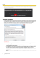
Preface For administrator registration At the time of first access to the camera (or at the time of initialization), the registration screen will be displayed. [User name (1 to 32 characters)] Enter the user name of the administrator. Available number of characters: 1 - 32 characters Unavailable characters: 2-byte characters, and 1-byte symbols " & : ; \ [Password (8 to 32 characters)]/[Retype password] Enter the administrator password.
Preface When the camera is reconnected to, an authentication window is displayed. Enter the registered user name and password to start operation. Viewer software In order to display H.265 (or H.264) images, send/receive audio to/from the camera, and play images saved on the SD memory card, the “Network Camera View 4S” (ActiveX®) viewer software must be installed.
Preface • The viewer software used on each PC should be licensed individually. The number of installations of the viewer software from the camera can be checked on the [Upgrade] tab of the “Maintenance” page (®page 209). Refer to your dealer for the software licensing.
Table of Contents Table of Contents 1 Operations ................................................................................................9 1.1 1.1.1 1.1.2 1.1.3 1.2 1.2.1 1.2.2 1.3 1.4 1.4.1 1.4.2 1.5 1.5.1 1.5.2 1.5.3 1.6 1.7 1.7.1 1.7.2 Monitor images on a PC ...................................................................................................9 Monitor images from a single camera ..............................................................................9 About the “Live” page .
Table of Contents 2.4.4.3 2.4.4.4 2.4.5 2.4.6 2.5 2.5.1 2.5.2 2.5.3 2.5.4 2.5.4.1 2.5.4.2 2.5.4.3 2.5.4.4 2.5.4.5 2.5.4.6 2.5.4.7 2.5.5 2.6 2.7 2.7.1 2.7.2 2.7.3 2.7.4 2.7.4.1 2.7.4.2 2.7.4.3 2.7.4.4 2.7.4.5 2.7.4.6 2.7.5 2.7.6 2.7.7 2.7.7.1 2.7.7.2 2.8 2.8.1 2.8.2 2.8.3 2.8.4 2.9 2.9.1 2.9.2 2.9.2.1 2.9.2.2 2.9.2.3 2.9.2.4 2.9.2.5 2.9.2.6 2.9.2.7 Installation of the certificate issued by CA ...................................................................85 Configuration of alteration detection .......
Table of Contents 2.9.2.8 2.9.3 2.9.3.1 2.9.3.2 2.9.3.3 2.9.3.4 2.9.3.5 2.9.3.6 2.9.4 2.9.4.1 2.9.5 2.9.6 2.9.6.1 Configure the QoS settings .......................................................................................176 How to configure HTTPS settings ................................................................................178 Select the certificate to use when accessing with HTTPS .........................................179 Obtaining the root certificate ..............................
1 Operations 1 Operations 1.1 Monitor images on a PC The following are descriptions of how to monitor images from the camera on a PC. 1.1.1 Monitor images from a single camera 1. Start up the web browser. 2. Enter the IP address designated using the Panasonic “IP Setting Software” in the address box of the browser. • Example when entering an IPv4 address: http://URL registered using IPv4 address http://192.168.0.
1 Operations 3. Press the [Enter] key on the keyboard. → The “Live” page will be displayed. Refer to page 12 for further information about the “Live” page. When “On” is selected for “User auth.”, the authentication window will be displayed before displaying live images for the user name and password entries. IMPORTANT • • It is recommended to change the password periodically. When displaying multiple H.265 (or H.264) images on a PC, images may not be displayed depending on the performance of the PC.
1 Operations When “On” is selected for “Stream transmission” max. 5fps When “Off” is selected for “Stream transmission” max.
1 Operations 1.1.2 About the “Live” page Note • The buttons and setting items displayed on the “Live” page can be changed depending on the user rights of the accessing user. You can set the user right settings from “User auth.” under “User mng.”. (®page 147) M A N O P Q R S T C D E F G U H I J K L [select language] pull-down-menu The camera’s display language can be selected. The default language can be set in the [Menu language] in the [Basic] settings.
1 Operations Stream(1)/Stream(2)/Stream(3)/Stream(4)/JPEG(1)/JPEG(2)/Multi-screen The image in the main area is displayed based on the contents set in Stream(1) – (4) (®page 93), JPEG(1) – (2) (®page 91), or Multi-screen (®page 126). Also the first stream displayed when you accessed the camera can be set from “Initial display stream” of the [Image] tab. For “Multi-screen”, you can set the “Initial display” in the [Multi-screen] tab.
1 Operations [Log/Play] button When the [Log/Play] button is clicked, the log list will be displayed and images saved on the SD memory card can be played. Refer to page 32 for further information about the log list and for how to play images on the SD memory card. [Viewer software] button Starts installation of the viewer software for display. This button will not be available if the viewer software is already installed on the PC, or if the “Automatic installation” of the [Viewer software (nwcv4Ssetup.
1 Operations When the audio reception is turned off, the button will turn into the button and audio from the camera will not be heard. Audio volume can be adjusted (Low/ Middle/ High) by moving the volume cursor . Note • When “Audio volume control mode” is set to “Adjust Mic input” in the setup menu, the volume cursor is not displayed when using “Audio recording”.
1 Operations Note • • *1 *2 16 When the camera is operated by a user with a low access level, images displayed on the screen may be changed temporarily. This does not affect operation of the camera. Depending on the PC in use, screen tearing* may occur when the shooting scene drastically changes due to the GDI restrictions of the OS. *A phenomenon in which portions of the screen are displayed out of alignment. Only operable by users whose access level is “1. Administrator”.
1 Operations 1.1.3 Monitor images from multiple cameras Images from multiple cameras can be displayed on a multi-screen. Images from 4, 9, and up to 16 cameras can be displayed simultaneously. To display images on a multi-screen, it is necessary to register cameras in advance. 4 cameras can be registered as a group and up to 4 groups (16 cameras) can be registered.
1 Operations 1. From the “Live view” pull-down menu in the “Live” page, select “Multi-screen”. → Images from the registered cameras will be displayed on a selected multi-screen (screen can be split up to 16 areas). The following are instructions when displaying on a 4-split screen. F G A B C D E “Live view” pull-down menu Select the image displayed in the main area. [Layout] pull-down menu Select from the pull-down menu to display images from cameras in multi-screens of 4 to 9 or even 16 screens.
1 Operations Note • • • • The frame rate may drop depending on the network environment and number of accessing users. If the image capture size specified for JPEG cannot be obtained, a JPEG image with an image capture size that could be obtained is displayed. Therefore, when JPEG images obtained with snap shot are displayed on a PC, the displayed image size may differ from the captured sized. When in full screen display, click¢ering and zoom are not available. When a video (H.265/ H.
1 Operations 1.2 Monitor images on a cellular phone/mobile terminal 1.2.1 Monitor images on a cellular phone It is possible to connect to the camera using a cellular phone via the Internet and monitor images (JPEG only) from the camera on the screen of the cellular phone. It is also possible to refresh images to display the latest image. IMPORTANT • • • • When the authentication window is displayed, enter the user name and password.
1 Operations Refresh control Press the dial key “5” or the [Manual Refresh] button to refresh the camera images. Press the [Auto Refresh] button to refresh the images from the camera in 5-second intervals. When the dial key “5” or the [Manual Refresh] button is pressed again, the refresh mode of the camera will return to manual refresh. IMPORTANT • Transmission will be periodically performed when “Auto Refresh” is selected for the camera image.
1 Operations The compatible mobile terminals are shown as follows. (As of April, 2018) – iPad, iPhone (iOS 4.2.1 or later) – Android™ mobile terminals When an Android terminal is used, an MJPEG format image is displayed by the Firefox® browser, and a JPEG format image is displayed by the standard browser. For further information about compatible devices, refer to our website (https://security.panasonic.com/support/info/
1 Operations 2. Click the button of the function that you want to operate. A B Resolution control AUX control Each function is explained below. Resolution control Press the button to display the buttons used to select the resolution on the screen. The resolution can be changed by selecting a resolution setting from the buttons.
1 Operations Images are displayed in the image capture size selected in “JPEG(1)” or “JPEG(2)” of [JPEG] on the [Image] tab. However, the images of the image capture size of “3072´1728”, “2560´1440”, “3072 ´2304”, and “2560´1920” cannot be displayed. AUX control Press the button to display the buttons used to operate the AUX output on the screen. The AUX output terminals can be controlled with the and buttons. This function is only displayed when [Terminal 3] is set to [AUX output] on the settings menu.
1 Operations Note • • • • • • • • *1 *2 You can change the image size displayed on the mobile terminal by accessing the following addresses. – Large display: http://IP address/cam/dl – Medium display: http://IP address/cam/dm – Small display: http://IP address/cam/ds When the resolution is changed by the resolution control, the displayed resolution changes but the image size remains the same.
1 Operations 1.3 Record images on the SD memory card manually Images displayed on the “Live” page can be recorded on the SD memory card manually. This button is operable only when “Manual” is selected for “Save trigger” on the [SD memory card] tab on the “Basic” page of the setup menu. (®page 76) It is possible to select “JPEG(1)”, “JPEG(2)”, “Stream(1)”, “Stream(2)”, “Stream(3)”, or “Stream(4)” on “Recording format” of the setup menu.
1 Operations • The destination to save image data is a fixed directory on Drive B (®page 237). When the [Start] button is clicked immediately after the [Stop] button is clicked, saving of images may not start. In this case, click the [Start] button again.
1 Operations 1.4 Action at an alarm occurrence The alarm action (camera action at an alarm occurrence) will be performed when the following alarms occur. 1.4.1 Alarm type • • • Terminal alarm: When connecting an alarm device such as a sensor to the alarm input terminal of the camera, the alarm action will be performed when the connected alarm device is activated. VMD alarm: When motion is detected in the set VMD area, the alarm action will be performed. *VMD stands for “Video Motion Detection”.
1 Operations configured in the “Alarm E-mail notification” section on the [Alarm] tab of the “Alarm” page (®page 132) and the [Advanced] tab of the “Network” page (®page 160). Notify of alarm occurrences to the designated addresses (Panasonic alarm protocol notification) This function is available only when a Panasonic device, such as the network disk recorder, is connected to the system.
1 Operations 1.5 Transmit images onto an FTP server Images can be transmitted to an FTP server. By configuring the following settings, transmission of images captured at an alarm occurrence or captured at a designated interval to an FTP server will become available. IMPORTANT • When using this function, set the user name and the password to access the FTP server to restrict users who can log into the FTP server. 1.5.
1 Operations image transmission function. Therefore, images may not be transmitted at the interval designated on the “FTP periodic image transmission” setting. 1.5.3 Save images on the SD memory card when images fail to transmit using the FTP periodic image transmission function Images that have failed to transmit using the FTP periodic image transmission can be saved automatically on the SD memory card.
1 Operations 1.6 Display the log list The history of various logs will be displayed in list form. • Alarm log: Logs of the alarm occurrences such as time and date of the alarm occurrences, the image recording period and the alarm type will be displayed. • Manual/Schedule log: Logs filed when images have been recorded manually or during the period of the schedule, and the image recording period will be displayed. • FTP trans.
1 Operations 2. Click the [Log/Play] button. → The log list will be displayed in a newly opened window (log list window). ① ② ③ ④ ⑤ IMPORTANT • Only a single user can operate the log list window. Other users cannot access the log list window. Time Displays the time period of the data recorded on the SD memory card. Event Select a log type to display on the log list. • All: All logs will be displayed. • Select: Only the logs of the selected log type will be displayed.
1 Operations Recording time Configure the time period of logs displayed on the log list. • From: Configure the starting period of logs displayed on the log list. – First recording: Displays from the first log recorded on the SD memory card. – Today: Displays the logs recorded today. – Yesterday: Displays the logs recorded from yesterday to the present day. – Last 7 days: Displays the logs recorded from 6 days ago to the present day.
1 Operations – COM: Alarm by command alarm – FTP: Logs saved from FTP periodic image transmission errors • [SD memory card]: Available capacity and the original capacity of the SD memory card will be displayed. • (Delete) button: Deletes log lists from all pages. When logs are searched for, only the searched logs are deleted. Images associated with deleted logs will also be deleted. IMPORTANT • • • If there are many recorded data files on the SD memory card, it may take time to delete all of them.
1 Operations 1.7 Playback of images on the SD memory card When clicking a time and date listed on the log list window, the “Live” page will turn to the “Playback” page. When images associated with the clicked time and date are on the SD memory card, the first image of them will be displayed. The display format varies depending on the “Recording format” of the SD memory card. IMPORTANT • • • • • Refresh interval of images may become slow during playback or download.
1 Operations Note • Enter the desired number of image and press the [Enter] key on the keyboard. The image of the designated number will be displayed. (REW) button Each time the button is clicked, the playback speed will change. When the button or the button is clicked during fast reverse playback, playback speed will return to the normal playback speed. (REV PLAY) button Images will be played in reverse sequential order.
1 Operations Note • When the mouse button is held down while the mouse pointer is on this button, the image number will be increased. When the mouse button is released, the increment of the image number will stop and the image number displayed at the moment when the mouse button is released will be displayed. (LAST) button The last image will be displayed. (Start) button The selected image will be downloaded onto the PC. Before downloading images, designate the destination directory in advance.
1 Operations 1.7.2 Playback “Stream(1)”/“Stream(2)”/“Stream(3)”/“Stream(4)” images saved to the SD memory card IMPORTANT • • Depending on the network environment, download of video data may fail. If downloading failed while playing images, you may be able to download images after stopping the currently played images and starting the download again. Depending on the network environment and status of the camera, you may not be able to operate each operation on this screen consecutively.
1 Operations (FF) button Each time this button is clicked, the playback speed will change. When the button is clicked during fast playback, playback speed will return to the normal playback speed. Note • The maximum speed of the fast playback varies depending on the setting of “Bit rate” - “Stream recording” of the SD memory card. Recorded audio will not be played back during fast playback.
1 Operations • • Depending on the status of the SD memory card or Windows Media Player, H.264 video data cannot be played back. For information on playing back H.265 video data, refer to the following Panasonic website below. https://security.panasonic.com/support/info/
2 Settings 2 Settings 2.1 About the network security 2.1.1 Equipped security functions The following security functions are featured in this camera. Access restrictions by the host authentication and the user authentication It is possible to restrict users from accessing the camera by setting the host authentication and/or the user authentication to “On”. (®page 147, page 150) Access restrictions by changing the HTTP port It is possible to prevent illegal access such as port scanning, etc.
2 Settings 2.2 Display the setup menu from a PC The settings of the camera can be configured on the setup menu. IMPORTANT • The setup menu is only operable by users whose access level is “1. Administrator”. Refer to page 147 for how to configure the access level. 2.2.1 How to display the setup menu 1. Display the “Live” page. (®page 9) 2. Click the [Setup] button on the “Live” page. → The window with the user name and password entry fields will be displayed. 3.
2 Settings 2.2.2 How to operate the setup menu A B Menu buttons Setup page 1. Click the desired button in the frame on the left of the window to display the respective setup menu. When there are tabs at the top of the “Setup” page displayed in the frame on the right of the window, click the desired tab to display and configure the setting items relating to the name of the tab. 2. Complete each setting item displayed in the frame on the right of the window. 3.
2 Settings 2.2.3 About the setup menu window A M B C D E F G H I J K L N [Setup] button Display the “Setup” page. [Live] button Display the “Live” page. [Easy Setup] button Displays the “Easy Setup” page. The “Easy Setup” page is used to set the connectivity to the Internet, as well as to set event actions such as alarm settings and camera action on alarm. (®page 47) [Basic] button Displays the “Basic” page.
2 Settings [Maintenance] button Displays the “Maintenance” page. System log check, firmware upgrade, status check and initialization of the setup menu can be carried out on the “Maintenance” page. (®page 208) [Support] button Displays the “Support” page. The “Support” page contains methods to display the Panasonic Support Website. (®page 216) Camera title The title of the camera whose settings are currently being configured will be displayed. Setup page Pages of each setup menu will be displayed.
2 Settings 2.3 Use Easy Setup [Easy Setup] The “Easy Setup” page uses simple operations to set the following: – Make the camera image available on the Internet – Set event actions such as recording of a schedule/alarm to the SD memory card The “Easy Setup” page consists of the [Internet] tab and [Event action] tab. 2.3.1 Configure the Internet settings [Internet] Click the [Internet] tab of the “Basic” page. (®page 43, page 44) The settings relating to UPnP (Auto port forwarding), DDNS (Viewnetcam.
2 Settings [Service] Select “Viewnetcam.com” or “Off” to determine whether or not to use “Viewnetcam.com”. By selecting “Viewnetcam.com” and clicking the [Set] button, the registration window for “Viewnetcam.com” will be displayed in a newly opened window. Follow the on-screen instructions to register with “Viewnetcam.com”. Refer to page 197 or the “Viewnetcam.com” website (http://www.viewnetcam.com/) for further information.
2 Settings The current settings are displayed here. You can set event actions for SD schedule recording/FTP periodic image transmission/alarm detection. Once the settings are completed in each setup menu, click the [Next] button to proceed. The setup flow is as follows. Note • If you click the [Next] button, the settings in the screen will be saved.
2 Settings Flow of event action setup Event function type: Select the trigger according to the purpose of setting. Alarm (®page 48) Schedule (®page 59) Terminal/VMD Event action setup: Configure the action conditions selected in the event function type setup. FTP img. trans. (®page 54) SD memory recording: JPEG/H.265/H. 264 (®page 54) SD memory recording: H.265/H.
2 Settings 2.3.2.1 Configure the schedule/alarm (event function type setup menu) Here, select the function type of the event. [Trigger] • Alarm: Select when setting the alarm detection settings. • Schedule: Select during “SD memory recording” or “FTP periodic image transmission”. • Default: Alarm [SD memory card format] To format the SD memory card, click the [Execute] button. Once you click the [Execute] button, the “Format” confirmation screen will be displayed.
2 Settings Alarm [Terminal 1] Determine how to use terminal 1. • Off: Not used. • Alarm input(TRM1): Receives terminal alarm input. – Close: An alarm is detected when the terminal status is changed to “On”. – Open: An alarm is detected when the terminal status is changed to “Off”. • Black & white input: Receives the black & white input. (When the input is set to “On”, the black & white mode is activated) • Auto time adjustment: Receives time setting through terminal input.
2 Settings Note • The duration of the alarm deactivation time can be specified for each type of alarm. For example, during the time when detections for “Terminal alarm 1” are not made, detections for “VMD alarm” can be made. [Next] button If you click the [Next] button, the alarm function type setup menu will be displayed. (®page 53) Note • If you click the [Next] button, the setting items in the screen are saved.
2 Settings [Back] button If you click the [Back] button the alarm setup menu will be displayed. (®page 51) 2.3.2.4 Alarm: Configure the details for image transfer or recording conditions A Set FTP transfer (FTP transfer setup menu) FTP transfer when an alarm is detected is set in this section. Refer to page 165 for information about how to set the above screen. For information about “Image compression rate upon alarm detection” and “Image quality upon alarm detection”, refer to “2.7.4.
2 Settings B Configure SD memory recording (JPEG) (JPEG recording setup menu) The SD memory recording (JPEG) when an alarm is detected is configure in this section. Refer to page 77 of 2.4.2 Configure the settings relating to the SD memory card [SD memory card] for information about how to set the above screen. [Next] button If you select “Alarm output” in the alarm setup menu and click the [Next] button, the alarm output setup menu will be displayed.
2 Settings Note • Refer to [Frame rate*] in “2.3.2.8 Schedule: Set SD memory recording (video recording setup menu)” for information about available frame rates and the bit rates that are set according to the frame rate. [Pre alarm (recording) duration] Determine whether or not to perform the pre alarm recording. Set the duration to save image data on the SD memory card.
2 Settings [Next] button If you click the [Next] button, the mail setup menu will be displayed. (®page 57) Note • If you click the [Next] button, the setting items in the screen are saved. [Back] button If you click the [Back] button, either the FTP transfer setup menu (®page 54), the JPEG recording setup menu (®page 55), or the video recording setup menu (®page 55) will be displayed. 2.3.2.
2 Settings • To configure e-mail related settings: Refer to page 160 for information about how to configure the above screen. [Set] button If you click the [Set] button, setup will be completed. [Back] button If you click the [Back] button, either the FTP transfer setup menu (®page 54), the JPEG recording setup menu (®page 55), the video recording setup menu (®page 55), or the alarm output setup menu (®page 56) will be displayed.
2 Settings 2.3.2.7 Schedule: Configure SD recording or FTP periodic image transmission (schedule function type setup menu) Here, the schedule type is selected as “SD memory recording” or “FTP periodic image transmission”. [Trigger] • SD memory recording: Records the H.265 (or H.264) image in the SD memory card at the scheduled • time. FTP periodic image transmission: Transmits the JPEG image to the FTP server at the scheduled time.
2 Settings [Audio recording] Determine whether or not to perform audio recording. • On: Saves audio data to videos (MP4 format). • Off: Does not save audio data to videos (MP4 format). • Default: Off Note • This setting is not available when “Interactive(Half-duplex)” is selected for “Audio transmission mode”. IMPORTANT • When the [Overwrite] setting is changed from “Off” to “On”, if the remaining capacity of the SD memory card is low, old images may be deleted in order to prepare to save new images.
2 Settings [Overwrite] Determine whether or not to overwrite images when the remaining capacity of the SD memory card becomes insufficient. • On: Overwrites when the remaining capacity of the SD memory card becomes insufficient. (The oldest image is the first to be overwritten.) • Off: Stops saving images on the SD memory card when the SD memory card becomes full.
2 Settings 2.3.2.9 Schedule: Configure FTP periodic image transmission (FTP periodic image transmission setup menu) The FTP periodic image transmission is configured in this section. • To configure FTP periodic image transmission settings: Refer to page 165 for information about how to configure the above screen. [Next] button If you click the [Next] button, the setup menu to set the FTP periodic image transmission schedule will be displayed.
2 Settings • To configure FTP periodic image transmission schedule settings: Refer to page 201 for information about how to set the above screen. [Set] button If you click the [Set] button, setup will be completed. [Back] button If you click the [Back] button, the FTP periodic image transmission setup menu will be displayed.
2 Settings Note • 64 FTP periodic image transmission will not be performed when “FTP periodic image transmission” is not selected in “Schedule mode”.
2 Settings 2.4 Configure the basic settings of the camera [Basic] The basic settings such as camera title, time and date, SD memory card and the logs can be configured on the “Basic” page. The “Basic” page has the [Basic] tab, the [SD memory card] tab, and the [Log] tab. 2.4.1 Configure the basic settings [Basic] Click the [Basic] tab on the “Basic” page. (®page 43, page 44) The settings such as the camera title, time and date, etc. can be configured on this page.
2 Settings [Menu language] Select the language to initially display when the camera is accessed from the following. Auto/English/Japanese/Italian/French/German/Spanish/Chinese/Russian/Portuguese • Auto: The language used by the browser is automatically selected. If the language used by the browser is not supported by the camera, English is selected. • Default: Auto The language displayed on the “Live” page can also be changed.
2 Settings [Time zone] Select a time zone corresponding to the location where the camera is in use. • Default: (GMT +09:00) Osaka, Sapporo, Tokyo [Summer time (daylight saving)] Select “In”, “Out” or “Auto” to determine whether or not to apply daylight saving time. Configure this setting if the summer time (daylight saving time) is applied in the location where the camera is in use. • In: Applies summer time. An asterisk (*) will be displayed on the left side of the displayed time and date.
2 Settings IMPORTANT • • If “150%” or “200%” is selected for [Character size], the frame rate may be lower than the specified value. Depending on the setting and the numbers of characters used for [Character size], and the setting and image capture size of images, characters displayed on the screen may be cut off. After completing the settings, confirm the result on the “Live” page.
2 Settings • • SD memory card error indicator/AF indicator (SD ERROR/AF) (red): Lights when data cannot be saved to the SD memory card. Also, when the auto focus function is used, the indicator flashes during focus adjustment and turns off when the adjustment is completed. SD MOUNT indicator (SD MOUNT) (green): Lights when data can be saved to the SD memory card. It blinks or is off when data cannot be saved to the SD memory card.
2 Settings IMPORTANT • • Use “Direct2D” with a computer that has the latest graphic driver version installed to it. When using “Direct2D”, set “Smoother live video display on the browser (buffering)” to “On”. If “Off” is selected for “H.264 Smoother live video display on the browser (buffering)”, “Direct2D” may not be very effective. Note • • • If your computer’s operating system is Windows 7 and the Aero function is disabled, “Direct2D” may not be very effective.
2 Settings Note • When “Manual” is selected, “Off”, “1 Frame Skip”, “2 Frames Skip”, “4 Frames Skip”, “6 Frames Skip”, or “8 Frames Skip” can be selected for frame skip by right-clicking on the “Live” page. The value selected here will revert to “Off” when the browser is closed. [Viewer software (nwcv4Ssetup.exe)] - [Contrast enhancement(RGB:0 to 255)] Select “On” or “Off” to determine whether or not to enhance the contrast of H.265 images or H.264 images on the “Live” page.
2 Settings 2.4.2 Configure the settings relating to the SD memory card [SD memory card] Click the [SD memory card] tab on the “Basic” page. (®page 43, page 44) The settings relating to the SD memory card can be configured on this page. Operating mode [SD memory card] Select “Use” or “Not use” to determine whether or not to use the SD memory card. • Default: Use [Audio recording] Select whether or not to save audio data when saving video data in MP4 format.
2 Settings [Remaining capacity notification] When the E-mail notification function or the Panasonic alarm protocol function is used to provide notification of the remaining capacity of the SD memory card, select a level to be notified at from the following. 50%/ 20%/ 10%/ 5%/ 2% • Default: 50% Note • Notification will be provided each time the remaining capacity goes below each of the specified values.
2 Settings [SD memory card password lock] Configure a password for the SD memory card. When configuring a password, devices other than the camera will be unable to write to or read the SD memory card. If the SD memory card is stolen or lost, the risk of recorded data being leaked can be reduced. [Set] When an SD memory card with no configured password is inserted, a password can be configured using the [Set] button. [Password]/[Retype password] Enter the password.
2 Settings Unavailable characters: " & [Status] Display the configuration status of the password lock. • Lock: A password is configured on the SD memory card, and the lock function is enabled. • Unlock: The lock function is disabled. Also display the password configuration status of SD memory card respectively. • Password is set.: The password is configured correctly. • Error(Unsupported SD memory card): A card that does not support password lock is inserted.
2 Settings IMPORTANT • • • If an SD memory card with an SD Speed Class other than 10 is used, 3072´2304, 2560´1920, 3072 ´1728, 2560´1440 cannot be selected for the image capture size of JPEG images. Set the bit rate of a stream selected in “Recording format” to 6 Mbps. If an SD memory card with an SD Speed Class 10 is used, set the bit rate of a stream selected in “Recording format” to 12 Mbps. For SD memory cards with an SD Speed Class 10, use a card that supports UHS-I.
2 Settings Note • • • When “Stream(1)”, “Stream(2)”, “Stream(3)”, or “Stream(4)” is selected for “Recording format”, “FTP periodic image transmission error” is unavailable. To enable alarms to occur, alarm settings must be configured in advance on the [Alarm] tab. When “JPEG(1)” or “JPEG(2)” is selected for “Recording format”, “Schedule” is unavailable.
2 Settings • Default: 1fps [Image saving interval/Number of images to be saved(Pre alarm)] - [Number of images to be saved] Select a number of pre alarm images to be saved on the SD memory card from the following. Off/1pic/2pics/3pics/4pics/5pics • Default: Off [Image saving interval/Number of images to be saved(Post alarm)] - [Image saving interval] When “Alarm input” or “Manual” is selected for “Save trigger”, select an interval (frame rate) of saving images on the SD memory card from the following.
2 Settings SD memory card warning detection conditions: After the total use time has exceeded 6 years and the number of overwrite times has exceeded 2000 SD memory card error detection conditions: Write error, read error, etc. • On: When a warning status is detected, the SD memory card error/error LED turns on. When an error status is detected, the SD memory card error/error LED starts flashing. • Off: Stops detection of warning or error status.
2 Settings • • • • After formatting the SD memory card, available size may be smaller than the total size since the default directory is automatically created in the SD memory card. Refer to our website (https://security.panasonic.com/support/info/ ) for latest information about the compatible SD memory cards. When repeatedly recording images on an SD memory card using the auto overwrite function, make sure to use an SD memory card with high reliability and durability.
2 Settings [Select certificate] Select the certificate to be used with alteration detection. Pre-installed: Selects a pre-installed certificate. CA: Selects a “CA Certificate”. Only displayed when the “CA Certificate” is installed. Default: Pre-installed [Additional info for detecting alteration] Select whether or not to give information for alteration detection to video files (MP4 format) to be saved on the SD memory card.
2 Settings 2.4.4 How to configure alteration detection settings The settings relating to alteration detection that detects when data in the SD memory card is altered or edited can be configured on this page. The alteration detection settings will be configured in the following procedure.
2 Settings 2. Click the [Execute] button. → The generation of CRT key will be started. When the generation is finished, the key size and generation time & date of the generated key will be displayed on “Current CRT key”. Note • • To change (or update) the generated CRT key, perform step 1 to 2. The CRT key and certificate issued by CA are valid in a set. When the CRT key is changed, it is necessary to re-apply for the certificate issued by CA.
2 Settings 1. Click the [Execute] button of “CA Certificate - Generate Certificate Signing Request”. → The “CA Certificate - Generate Certificate Signing Request” dialog box will be displayed. 2. Enter the information of the certificate to be generated. Description Item Available number of characters [Common Name] Enter the camera address or host name. 64 characters [Country] Enter the country name. 2 characters (Country code) [State] Enter the state name.
2 Settings 2.4.4.3 Installation of the certificate issued by CA IMPORTANT • • If the CSR file is not generated, it is impossible to install the certificate (CA certificate) issued by CA. For the installation of the certificate issued by CA, the CA certificate issued by CA is required. 1. Click the [Browse...] button of “CA Certificate - Certificate install”. → The [Open] dialog box will be displayed. 2. Select the certification file and click the [Open] button. Then, click the [Execute] button.
2 Settings 2.4.4.4 Configuration of alteration detection 1. Select “On” for “Additional info for detecting alteration”, and click the [Set] button. 2. Extensive information for alteration detection will be added to video files (MP4 format) recorded after changing the setting. IMPORTANT • When the “Additional info for detecting alteration” setting is changed, manual recording on the SD memory card will stop. Start manual saving again as necessary.
2 Settings 2.4.5 Access copy images saved on the SD memory card onto the PC [SD memory card images] Click the [SD memory card] tab on the “Basic” page. (®page 43, page 44) The following are descriptions of how to copy images saved on the SD memory card onto the PC. It is necessary in advance to select “Allow” for “FTP access to camera” on the [Network] tab of the “Network” page.
2 Settings Possible number of JPEG images that can be saved on the SD memory card (as indications) For possible numbers of JPEG images that can be saved on the SD memory card, refer to our website below. https://security.panasonic.com/support/info/ Possible duration of stream images (H.265 or H.264) that can be saved on the SD memory card (as indications) For possible duration of stream images (H.265 or H.264) that can be saved on the SD memory card, refer to our website below.
2 Settings 2.4.6 Configure the directory of the PC that images will be downloaded to [Log] Click the [Log] tab on the “Basic” page. (®page 43, page 44) The directory of the PC that images recorded on the SD memory card will be downloaded to can be configured in this section. Alarm The settings related to the directory of the PC that recorded images of when alarms occur will be downloaded to can be performed.
2 Settings Note • When “Stream(1)”, “Stream(2)”, “Stream(3)”, or “Stream(4)” is selected for “Recording format”, “FTP periodic image transmission error” is unavailable. 2.5 Configure the settings relating to images and audio [Image/Audio] The settings relating to JPEG, H.265, and H.264 images such as the settings of image quality, audio, etc. can be configured on this page. The “Image/Audio” page has the [Image] tab, the [Image quality] tab, and the [Audio] tab. 2.5.
2 Settings 2.5.2 Configure the settings relating to JPEG images [Image] Click the [Image] tab on the “Image/Audio” page. (®page 43, page 44) "Live" page (Initial display) Configure the settings relating to the initial images displayed on the “Live” page. [Initial display stream] Select the image to display on the “Live” page from the following.
2 Settings Image capture mode • JPEG(1) JPEG(2) 4:3 mode 3072´2304 2560´1920 1280´960 800´600 VGA 400´300 QVGA 1280´960 800´600 VGA 400´300 QVGA 16:9 mode 3072´1728 2560´1440 1920´1080 1280´720 640´360 320´180 1920´1080 1280´720 640´360 320´180 Default: – JPEG(1): 2560´1440 – JPEG(2): 1280´720 [Image quality] Select the image quality of JPEG images for each image capture size.
2 Settings 2.5.3 Configure the settings relating to Stream [Image] Click the [Image] tab on the “Image/Audio” page. (®page 43, page 44) Configure the settings relating to H.265 (or H.264) image such as “Max bit rate (per client)”, “Image capture size”, “Image quality”, etc. in this section. Refer to page 91 for the settings relating to JPEG images. Stream(1)/ Stream(2)/ Stream(3)/ Stream(4) [Stream transmission] Select “On” or “Off” to determine whether or not to transmit H.265 (or H.264) images.
2 Settings • • • On: H.265 (or H.264) images and audio will be transmitted using the HTTP port. Refer to page 157 for further information about the HTTP port number settings. Off: H.265 (or H.264) images and audio will be transmitted using the UDP port. Default: Off Note • • • • When “On” is selected, only “Unicast port (AUTO)” will be available for “Transmission type”. When “On” is selected, it may take time to start displaying stream images.
2 Settings • • • Frame rate: H.265 (or H.264) images will be transmitted with the frame rate selected for “Frame rate*”. Best effort: In accordance with the network bandwidth, H.265 (or H.264) images will be transmitted with the maximum bit rates that are set for “Max bit rate (per client)*”. Default: Frame rate Note • When “Frame rate” is set for “Transmission priority”, number of users who can access the camera may be limited. [Frame rate*] Select a frame rate from the following.
2 Settings • • • • 3072´1728: 1024kbps* - 24576kbps* 2560´1440: 768kbps* - 24576kbps* 2560´1920: 768kbps* - 24576kbps 3072´2304: 1536kbps* - 24576kbps* Note • • The bit rate for “Stream” is restricted by “Bandwidth control(bit rate)” on the [Network] tab on the “Network” page (®page 155). When a value with “*” attached is set, images may not be streamed. Depending on the number users connecting at the same time or the combination of features used, the bit rate may be lower than the configured value.
2 Settings [Refresh interval] Select an interval (I-frame interval; 0.2 - 5 seconds) to refresh the displayed H.265 (or H.264) images from the following. If using under a network environment with frequent error occurrences, shorten the refresh interval for H.265 (or H.264) to diminish image distortions. However, the refresh interval may be longer than the set value. 0.2s/ 0.25s/ 0.33s/ 0.
2 Settings • • • Available IPv4 address: 224.0.0.0 - 239.255.255.255 Available IPv6 address: Multicast address starting with “FF” Default: – Stream(1): 239.192.0.20 – Stream(2): 239.192.0.21 – Stream(3): 239.192.0.22 – Stream(4): 239.192.0.23 Note • Enter a multicast IP address after checking available multicast address. [Multicast port]*2 Enter the multicast port number (used to transmit images from the camera). • Available port number: 1024 - 50000 (Only even numbers are available.
2 Settings 2.5.4 Configure the settings relating to image adjust, zoom/focus, privacy zone, VIQS, and lens distortion compensation [Image quality] Click the [Image quality] tab on the “Image/Audio” page. (®page 43, page 44) When the [Setup>>] button of each setting item is clicked, the detailed settings menu will be displayed in a newly opened window. The detailed settings can be configured while monitoring images displayed on the [Image quality] tab.
2 Settings 2.5.4.1 Configure the settings relating to image quality (“Image adjust” setup menu) Click the [Setup>>] button of “Image adjust” on the [Image quality] tab of the “Image/Audio” page. (®page 99) The settings relating to image quality can be configured with the setup menu displayed in a newly displayed window. When the values are changed, the changed values will be applied to the currently displayed image on the [Image quality] tab.
2 Settings • • • On: The super dynamic function will work. Off: The super dynamic function will not work. Default: On Note • • • When “On” is selected for “Super Dynamic(SD)”, the frame rate is restricted a maximum of 15fps. When the following are observed depending on the light condition, select “Off” for “Super Dynamic(SD)”.
2 Settings A B A. Subject in the dark area is hard to notice... B. Subject in the bright area is washed out... C. Creates a clearer image by digitally combining images C [BLC/ HLC] Select from the following. When “On” is selected for “Super Dynamic(SD)” or when “On” is selected for “Intelligent Auto”, this setting is not available. • Back light compensation (BLC): Activates the back light compensation (BLC) function. • High light compensation(HLC): Activates the high light compensation (HLC) function.
2 Settings Light control mode [Light control mode] Select the light control mode from the following. • Outdoor scene: Depending on the brightness level (illuminance), the iris will automatically be controlled together with the shutter speed adjustment to control light. When shooting a bright subject such as outdoor, etc., select this parameter. Be aware that flicker may occur when a subject is under fluorescent lighting.
2 Settings Note • • When “On” is selected for “Super Dynamic(SD)”, “Max.1/2000s” and “Max.1/4000s” are not available. When “0” is selected for “Maximum gain”, “Max.2/30s” or higher is not available. [Light control speed] Adjust the light control speed. If you move the slider in the “+” direction, the light control speed will increase. If you move the slider in the “-” direction, the light control speed will decrease. Click the [Reset] button to reset to the default setting.
2 Settings • The color mode and the black white mode may not be switched automatically depending on the environment. In such a case, use the schedule function to switch the color and the black white mode. For how to set up, refer to the following Panasonic support website. https://security.panasonic.com/support/info/ [Level] Select the threshold illuminance level (brightness) to switch between the color mode and the black & white mode.
2 Settings • • • • ATW1: Selects the automatic tracing white balance mode. The camera will constantly check the color temperature of the light source and adjust the white balance automatically. Operating color temperature range is approx. 2,700 K to 6,000 K. ATW2: Selects the automatic tracing white balance mode under a sodium lamp. The camera will adjust the white balance automatically under a sodium lamp. Operating color temperature range is approx. 2,000 K to 6,000 K.
2 Settings [Motion priority level] Adjusts the motion priority level when “Intelligent Auto” is activated. If you move the slider in the “+” direction, it becomes difficult for the moving subjects to blur, but the noise of dark subjects increases. If you move the slider in the “-” direction, it becomes easier for the moving subjects to blur, but the noise of dark subjects decreases. Click the [Reset] button to reset to the default setting.
2 Settings If you move the slider in the “-” direction, the dark parts of the image will become darker. Click the [Reset] button to reset to the default setting. • Default: 128 IMPORTANT • The “adaptive black stretch” settings may cause the noise in the darker parts to increase, and the parts around borders between the darker parts and the brighter parts may become darker/brighter than the other darker/brighter parts. [Adaptive highlight stretch] Adjust the brightness of the bright parts of the image.
2 Settings [Pedestal level] Adjust the black level of images by moving the slider. When the slider is moved to the “+” direction, images will become brighter. When the slider is moved to the “-” direction, images will be darker. Click the [Reset] button to reset the color to the default. • Default: 128 [DNR] The digital noise reduction function reduces noise automatically under the condition of low illuminance. If you move the slider in the “+” direction, the noise reduction effect is strengthened.
2 Settings 1. Display the “Image adjust” setup menu. (®page 99) 2. Click “+” on the left of “Super Dynamic(SD)” to display the detailed SD menu.
2 Settings 3. Click the [Start] button of “Mask area”. → Borders will appear and the image displayed on the [Image quality] tab will be divided into 48 (8´6).
2 Settings 4. Click the divided areas to be masked. → The clicked areas will be masked and will become white. To cancel masking, click the area again. 5. Click the [End] button after completing masking areas. → The borders on the image displayed on the [Image quality] tab will disappear. IMPORTANT • • The mask area may move out of alignment if the setting for “Image capture mode” of the [Image] tab or “Image rotation” of the [Basic] tab is changed after the mask area has been configured.
2 Settings 2.5.4.3 Adjust the zoom and focus Click the [Setup>>] button of “Zoom/Focus adjustment” on the [Image quality] tab of the “Image/Audio” page. (®Page 99) Zoom/Focus adjustment It is possible to adjust the angular field of view using the zoom and the extra optical zoom. Adjust the focus setting by moving the lens focus to the appropriate position. Manual and auto adjustments are available. [Zoom ratio designation] The zoom and focus can be adjusted at the same time.
2 Settings Note • • The red area of the slider and angular field of view adjustment outline represents optical zoom, and the yellow area represents extra optical zoom. If you click the button or button of [Manual zoom adjustment], [Zoom ratio designation] cannot be operated. To perform [Zoom ratio designation], click the [Load] button, or the zoom adjustment]. button of [Manual [Manual zoom adjustment] The zoom can be adjusted manually.
2 Settings – – – – – – – – • when the subject moves a lot when there are large changes to the lighting intensity when the light level is low when the subject or location is extremely bright or reflective when viewing through windows when the dome cover is in a location where it can easily become dirty locations where there is not much contrast such as a white wall when there is harsh flickering When images in the near-infrared light area change from color to black & white, images may be out of focus due
2 Settings 2.5.4.4 Configure the settings relating to the privacy zone (“Privacy zone” setup menu) Click the [Setup>>] button of “Privacy zone” on the [Image quality] tab of the “Image/Audio” page. (®page 99) When there is a zone that you do not want to display, set the zone as a privacy zone not to be displayed. Up to 8 privacy zones can be set. [Area] The privacy zone will be set when an area is designated by dragging the mouse. Each zone can be overlapped.
2 Settings IMPORTANT • After configuring the privacy zone, the privacy zone may move out of alignment if the setting for “Image capture mode” of the [Image] tab or “Image rotation” of the [Basic] tab is changed.
2 Settings 2.5.4.5 Configure the VIQS setting Click the [Setup>>] button of “VIQS” on the [Image quality] tab of the “Image/Audio” page. (®page 99) VIQS is an abbreviation of Variable Image Quality on Specified area and is a feature that enables you to change the images of a specified area. It is possible to enhance the image quality of the specified range within a shooting area (image). It is also possible to moderate the image data size by lowering the image quality of other areas.
2 Settings • Default: Off [Delete] button Deletes the VIQS area. Click the button to delete the VIQS area. [Level] Configure the difference level in the image quality between specified areas and non-specified areas. The greater the difference level, the more the image quality of the non-specified area is reduced. This makes it possible to moderate the image data size. 0 Min./ 1/ 2/ 3/ 4/ 5 Normal/ 6/ 7/ 8/ 9 Max.
2 Settings 2.5.4.6 Configure the VIQS area The VIQS area is specified by following the steps below. 1. Drag the mouse on the screen to specify the area (up to 8 areas). → The specified area is set to area “1(White)”, and the outline is displayed. The areas are set in the area number order from number 1. The color next to the area number show the color of the corresponding outline. 2. Configure the difference level in the image quality between specified areas and non-specified areas.
2 Settings IMPORTANT • • • • No setting contents are determined unless the [Set] button is clicked. To check the image after configuring VIQS, display an H.265 (or H.264) image on the “Live” page, or press the [Confirm] button under “Stream”. The outputted bit rate changes depending on the subject. Confirm the bit rates with actual subjects used when operating the camera. If the larger range is specified, the output bit rate increases. Check the current output bit rate to decide the area size.
2 Settings 2.5.4.7 Configure the settings relating to lens distortion compensation Click the [Setup>>] button of “Lens distortion compensation” on the [Image quality] tab of the “Image/Audio” page. (®Page 99) Distortion correction can be performed using lens distortion compensation. The amount of compensation performed can be adjusted. • • 122 The degree of distortion compensation varies depending on the image capture mode.
2 Settings 2.5.5 Configure the settings relating to audio [Audio] Click the [Audio] tab on the “Image/Audio” page. (®page 43, page 44) The settings relating to audio can be configured on this page. Note • • Images and audio will not be synchronized. Therefore, images and audio may not always match. Audio may be interrupted depending on the network environment. Mic input [Mic input volume] Set the audio volume for input into the camera.
2 Settings • Default: High [Audio bit rate] Set the audio compression bit rate. [G.726(Live)]: 16kbps/32kbps [G.711(Live)]: 64kbps (cannot be changed) [AAC-LC(Live/Recording)]: 64kbps/96kbps/128kbps • Default: – [G.
2 Settings • Default: Middle [Audio output interval (PC to Camera)]: Select an interval for audio transmission from the following. 160ms/ 320ms/ 640ms/ 1280ms • Default: 640ms Note • • • When a shorter interval is selected, the delay time will be shorter. When a longer interval is selected, audio interruption may be diminished even though the delay time will be longer. Select the interval according to the network environment.
2 Settings 2.6 Configure the multi-screen settings [Multi-screen] The cameras from which images are to be displayed on a multi-screen can be registered on the “Multi-screen” page. (®page 43, page 44) [IP address] Enter the IP address or the host name of the camera to be used for the multi-screen. 4 cameras can be registered as a group and up to 4 groups (16 cameras) can be registered.
2 Settings IMPORTANT • • When accessing the camera using the HTTPS protocol, install the pre-installed certificate or the CA certificate of the camera to display images on the monitor. (®page 188) This camera is specified when “selfcamera” is displayed for the IP address or host name. Note • • For further information about “Network Camera Recorder with Viewer Software Lite”, which is suited to viewing images from several cameras, refer to our website (https://security.panasonic.
2 Settings 2.7 Configure the alarm settings [Alarm] The settings relating to alarm occurrences such as settings for the alarm action at an alarm occurrence or alarm images, the VMD area settings, and the alarm occurrence notification can be configured on this page. The “Alarm” page has the [Alarm] tab, the [VMD area] tab, and the [Notification] tab. 2.7.1 Configure the settings relating to the alarm action [Alarm] Click the [Alarm] tab on the “Alarm” page.
2 Settings • • – Open: An alarm is detected when the terminal status is changed to “Open”. Alarm output: Alarm output will be carried out according to the settings for “Output terminal” (®page 130). Default: Off [Terminal 3] Determine how to use terminal 3. • Off: Not used. • Alarm input(TRM3): Receives alarms. When “Alarm input” is selected, a pull-down menu for “Close” and “Open” is displayed. – Close: An alarm is detected when the terminal status is changed to “Close”.
2 Settings Note • The duration that alarm detections are not made can be managed for each type of alarm. For example, during the time when detections for command alarms are not made, detections for VMD alarm can be made. 2.7.2 Configure the settings relating to the output terminal [Alarm] Click the [Alarm] tab on the “Alarm” page. (®page 43, page 44) The settings relating to the output terminal can be configured in this section.
2 Settings • • When an SD memory card error is detected, the [Alarm occurrence indication] button on the “Live” page blinks. If you click on the [Alarm occurrence indication] button, the button will be hidden. Output signals from the output terminal for [SD memory card error] differ depending on the settings of [Terminal state upon alarm detection].
2 Settings AUX title [AUX (Up to 10 characters)] Enter the name for “AUX” on the “Live” page. • Unavailable characters: " & • Default: AUX [Open (Up to 5 characters)] Enter the name for “Open” of “AUX” on the “Live” page. • Unavailable characters: " & • Default: Open [Close (Up to 5 characters)] Enter the name for “Close” of “AUX” on the “Live” page. • Unavailable characters: " & • Default: Close Note • • When AUX setting is not available, AUX name cannot be changed.
2 Settings [Alarm image FTP transmission] Click “FTP setup >>” to display the setup menu that can configure the settings relating to FTP transmission when an alarm occurs. The setup menu will be displayed in a newly opened window. (®page 135) [Alarm image recording(SD memory card)] Click “SD memory card setup >>” to display the setup menu that can configure the settings relating to recording images on an SD memory card when an alarm occurs. The setup menu will be displayed in a newly opened window.
2 Settings 2.7.4.2 Configure settings relating to alarm E-mail notifications Click “E-mail server >>” of “Camera action on alarm” on the [Alarm] tab of the “Alarm” page. (®page 132) Refer to page 160 for information on configuration for these settings.
2 Settings 2.7.4.3 Configure settings relating to FTP transmissions of alarm images Click “FTP setup >>” of “Camera action on alarm” on the [Alarm] tab of the “Alarm” page. (®page 132) Refer to page 165 for information on configuration for these settings.
2 Settings 2.7.4.4 Configure settings relating to recording to an SD memory card when an alarm occurs Click “SD memory card setup >>” of “Camera action on alarm” on the [Alarm] tab of the “Alarm” page. (®page 132) Refer to page 72 for information on configuration for these settings.
2 Settings 2.7.4.5 Configure settings relating to Panasonic alarm protocol notification when an alarm occurs Click “Panasonic alarm protocol notification >>” of “Camera action on alarm” on the [Alarm] tab of the “Alarm” page. (®page 132) Refer to page 143 for information on configuration for these settings.
2 Settings 2.7.4.6 Configure settings relating to HTTP alarm notification when an alarm occurs Click “HTTP alarm notification setup >>” of “Camera action on alarm” on the [Alarm] tab of the “Alarm” page. (®page 132) Refer to page 145 for information on configuration for these settings. 2.7.5 Configure the VMD settings [VMD area] Click the [VMD area] tab on the “Alarm” page. (®page 43, page 44) The video motion detection areas can be set on this page. Up to 4 areas can be set.
2 Settings • The motion detection function is not the dedicated function to prevent thefts, fires, etc. We are not responsible for any accidents or damages that may occur. [Area] When selecting a VMD area in the screen, it will be numbered as area 1. (Subsequent areas will be numbered in the order of selection.) [All areas] button When the [All areas] button is clicked, the whole area will become the VMD area, and “1(White)” will be automatically applied to “Area”.
2 Settings • Default: 1 [Detection sensitivity] Adjust the sensitivity of motion detection in the VMD area using the slider. The settings can be configured for each area individually. The larger the value is set, the higher the sensitivity level becomes. The current value (1 (low) - 15 (high)) will be displayed below the slider. • Default: 8 [Delete] button Click the [Delete] button corresponding to the area to be deleted. The outline of the selected area will be deleted.
2 Settings 1. Set the video motion detection area by dragging the mouse on the screen. → The designated area will become the VMD area “1(White)” and the outline will be displayed. When 2 - 4 VMD areas are set, each area will be numbered in order. The areas will be identified by the respective outline colors. The “Status” of the outline to be set for the area will become “On”. 2. Adjust “Detection area” and “Detection sensitivity” using the slider.
2 Settings 6. Click the [Set] button. → The edited settings will be applied. 2.7.7 Configuration of the settings relating to alarm notification [Notification] Click the [Notification] tab on the “Alarm” page. (®page 43, page 44) The settings relating to Panasonic alarm protocol and HTTP alarm notification can be configured in this section.
2 Settings 2.7.7.1 Configure the settings relating to Panasonic alarm protocol Panasonic alarm protocol notification [Panasonic alarm protocol] Select “On” or “Off” to determine whether or not to provide notification by Panasonic alarm protocol according to the settings for the “Alarm” and “Diag.” checkboxes of “Destination of notification” below. – When an alarm is detected (“Alarm”) – When a notification of the remaining capacity of the SD memory card has been provided (“Diag.
2 Settings – When the SD memory card cannot be recognized (“Diag.”) • Default: Off Note • When “On” is selected, notification of the alarm occurrence will be provided to the registered destination server addresses in order (to IP address 1 first, to IP address 8 last). [Additional alarm data] Determine whether or not to send notifications for VMD alarm detection area numbers with the Panasonic alarm protocol by selecting On/Off.
2 Settings IMPORTANT • • When entering the host name of the “Destination server address”, the DNS settings on the [Network] tab of the “Network” page must be configured. (®page 155) Confirm that the destination IP addresses are registered correctly. When a registered destination does not exist, notification may be delayed. 2.7.7.
2 Settings • • Available number of characters: 0 - 63 characters Unavailable characters: " & : ; \ [Password] Enter the password to access the HTTP server. • Available number of characters: 0 - 63 characters • Unavailable characters: " & [Notification data] Enter the notification data to add after the destination HTTP server addresses set in [Address 1] - [Address 5]. • Available characters: Alphanumeric characters • Default: /cgi-bin/comalarm.
2 Settings 2.8 Configure the settings relating to the authentication [User mng.] The settings relating to the authentication such as users and PCs restrictions for accessing the camera with a PC or cellular phone/mobile terminal can be configured on the “User mng.” page. The “User mng.” page has 4 tabs; the [User auth.] tab, the [Host auth.] tab, [IEEE 802.1X] tab and [Data encryption] tab. 2.8.1 Configure the settings relating to the user authentication [User auth.] Click the [User auth.
2 Settings Note • When user authentication has failed to pass (authentication error) 8 times within 30 seconds using the same IP address (PC), access to the unit will be denied for a while. [User auth.] Select “On” or “Off” to determine whether or not to authenticate the users. • Default: On [Guest User] Select whether or not to set Guest User. If you select “Use”, you can set which functions are available or unavailable for guest users for whom user authentication has not been performed.
2 Settings [Authentication] Set the user authentication method. • Digest or Basic: Uses “Digest or Basic” authentication. • Digest: Uses “Digest” authentication. • Basic: Uses “Basic” authentication. • Default: Digest Note • • • To enhance the security, it is recommended to select “Digest” for “Authentication method”. If “Digest or Basic” or “Basic” is selected, leakage of the user name and the password may occur.
2 Settings [Access level] Select the available functions based on the user access level (camera control, live view, guest user). • Default: – Camera control: All are checked – Live only: All are not checked – Guest User: All are not checked Note • • • If you have set “User authentication” to “Off”, and “Guest User” to “Not use”: The “Access Level” item cannot be set. And, while all the live operation buttons are displayed, the [Setup] buttons require authentication.
2 Settings The restriction settings of PCs (IP address) from accessing the camera can be configured on this page. [Host auth.] Select “On” or “Off” to determine whether or not to authenticate the host. • Default: Off IMPORTANT • • Set “Host auth.” to “On” after registering the IP address of the PC. If “On” is selected for “User auth.”, the user authentication is required regardless of the host authentication settings. [IP address] Enter the IP address of the PC to be allowed to access the camera.
2 Settings 2.8.3 Configure IEEE 802.1X [IEEE 802.1X] Click the [IEEE 802.1X] tab on the “User mng.” page. (®For menu display and how to operate, refer to page 43, page 44) The settings relating to IEEE 802.1X can be configured on this page. [IEEE 802.1X] Select “On” or “Off” to determine whether or not to perform port authentication using IEEE 802.1X. • Default: Off [User name] Enter the user name to access the authentication LAN switch.
2 Settings Click the “-” mark on the left of an expanded item to return to the screen displayed before the item was expanded. [Data encryption (Batch change)] Select “On” or “Off” to determine whether or not to activate data encryption. • On: Activates data encryption. Encrypts Stream(1), Stream(2), Stream(3), Stream(4), JPEG(1), JPEG(2), and “AAC-LC” audio. • Off: Deactivates data encryption.
2 Settings • If you confirm streams with data encryption set to “On” on the “Live” page, password entry for decryption is displayed. If you correctly enter the “Encryption password” that was set, you will be able to view images. When “Mic input”, “Interactive(Full-duplex)”, or “Interactive(Full-duplex)” is selected for [Audio transmission mode], only audio may be played until the password is entered.
2 Settings 2.9 Configuring the network settings [Network] The network settings can be configured on the “Network” page. The “Network” page has the [Network] tab and the [Advanced] tab. 2.9.1 Configure the network settings [Network] Click the [Network] tab on the “Network” page. (®page 43, page 44) The following information is required to configure the network settings. Contact the network administrator or your Internet service provider.
2 Settings IPv4 network [Network Settings] Select the method of how to configure the IP address from the following. • Static: The IP address is configured by entering manually on “IP address(IPv4)”. • DHCP: The IP address is configured using the DHCP function. • Auto(AutoIP): The IP address is configured using the DHCP function. When the DHCP server is not found, the IP address is automatically configured.
2 Settings IPv6 network [Manual] Select “On” or “Off” to determine whether or not to manually configure the IP address for IPv6 network (IPv6 address). • On: Enter an IPv6 address manually. • Off: Manual entry of an IPv6 address will become unavailable. • Default: Off [IP address(IPv6)] When “On” is selected for “Manual”, manual entry of the IPv6 address is required. Do not enter an address already in use.
2 Settings [Max RTP packet size] Select “Unlimited(1500byte)” or “Limited(1280byte)” to determine whether or not to restrict the RTP packet size when viewing images from the camera using the RTP protocol. It is recommended to use with the default “Unlimited(1500byte)”. When the RTP packet size is restricted in the network line in use, select “Limited(1280byte)”. Refer to the network administrator for further information about the maximum packet size in the network line.
2 Settings • To access the camera via the Internet by connecting the camera to a router, it is necessary to assign a respective HTTP port number for each camera and address translation by using the port forwarding function of the router. For further information, refer to the operating instructions of the router in use. Enter [Global IP address + : (colon) + port number] in the "Address" box of the browser via the Internet. vvv.xxx.yyy.zzz:50000 vvv.xxx.yyy.zzz:50001 WAN Global address vvv.xxx.yyy.
2 Settings 2.9.2.
2 Settings [E-mail notification] Select “On” or “Off” to determine whether or not to provide notification by E-mail according to the settings for the “Alarm” and “Diag.” checkboxes of “Destination of notification” below. – When an alarm is detected (“Alarm”) – When a notification of the remaining capacity of the SD memory card has been provided (“Diag.”) – When the SD memory card has become full (“Diag.”) – When the SD memory card cannot be recognized (“Diag.
2 Settings Note • • • When you don’t know the authentication method to send E-mails, refer to the network administrator. User name Enter the user name to access the server. – Available number of characters: 0 - 32 characters – Unavailable characters: " & : ; \ Password Enter the password to access the server. – Available number of characters: 0 - 32 characters – Unavailable characters: " & [Sender’s E-mail address] Enter the E-mail address of a sender.
2 Settings • • • Available number of characters: 0 - 50 characters Use the camera title: The camera title will be displayed in the e-mail subject. Cause of alarm: Adds the cause of alarm to the E-mail subject. [E-mail body] Enter the E-mail body. • Available number of characters: 0 - 200 characters • Cause of alarm: The cause of alarm %p% is added in the e-mail body. %p% is replaced by the cause of alarm and sent.
2 Settings Example of e-mail notification An e-mail format in which the camera title check box is specified in the e-mail subject and the cause of alarm/ occurrence time are specified in the e-mail body Example e-mail: A Subject: XXXXX B E-mail body: An "Entrance" alarm occured at 19:13:24 C The alarm occurrence time is assigned. The camera title is used as the e-mail subject. The name set for Terminal names 1 to 3, which is the cause of alarm, is assigned to the name.
2 Settings 2.9.2.2 Configure the settings related to FTP transmission FTP [Alarm image FTP transmission] Select “On” or “Off” to determine whether or not to transmit the alarm image to the FTP server. • Default: Off [Directory name] Enter the directory name where the alarm images are to be saved. For example, enter “/ALARM” to designate the directory “ALARM” under the root directory of the FTP server.
2 Settings [File name] Enter the file name used for the alarm image to be transmitted to an FTP server. The file name will be as follows. File name: [“Entered file name” + “Time and date (year/ month/ day/ hour/ minute/ second)”] + “Serial number” • Available number of characters: 1 - 32 characters • Unavailable characters: " & * / : ; < > ? \ | • Terminal 1: Transmit the image to the FTP server when an alarm occurs in Terminal 1.
2 Settings Image capture size QVGA 40 50 50 50 50 50 50 50 50 50 400x300 30 30 40 50 50 50 50 50 50 50 VGA 10 20 20 30 30 40 50 50 50 50 800x600 9 10 10 20 20 30 30 50 50 50 1280x960 5 6 7 8 10 10 10 20 30 40 320x180 50 50 50 50 50 50 50 50 50 50 640x360 20 30 40 50 50 50 50 50 50 50 1280x720 7 8 10 10 10 20 20 30 40 50 [Post alarm] • Transmission interval • • Select the transmission interval for the alarm image tra
2 Settings [File name] Enter the file name (name of the image file to be transmitted) and select the naming option from the following. Name w/time&date: File name will be [“Entered file name” + “Time and date (year/ month/ day/ hour/ minute/ second)” + “Serial number (starting from 00)”]. • Name w/o time&date: File name will be the characters entered for “File name” only. When “Name w/o time&date” is selected, the file will be overwritten each time a file is newly transmitted.
2 Settings 20, 23, 25, 42, 53, 67, 68, 69, 80, 110, 123, 161, 162, 443, 995, 10669, 10670 [FTP mode] Select “Passive” or “Active” for the FTP mode. Normally, select “Passive”. When it is impossible to connect after select “Passive”, try to connect after selecting “Active”. • Default: Passive 2.9.2.3 Configure the settings relating to the NTP server The settings relating to the NTP server such as the NTP server address, port number, etc. can be configured on this page.
2 Settings [NTP server address] When “Manual” is selected for “NTP server address setting”, enter the IP address or the host name of the NTP server. • Available number of characters: 1 - 128 characters • Available characters: Alphanumeric characters, the colon (:), the period (.), the underscore (_), and the hyphen (-). • Default: None (blank) IMPORTANT • When entering the host name for “NTP server address”, it is necessary to configure the DNS settings on the [Network] tab of the “Network” page.
2 Settings • • The UPnP function is available when the camera is connected to the IPv4 network. IPv6 is not supported. To check if auto port forwarding is properly configured, click the [Status] tab on the “Maintenance” page, and check that the “Enable” is displayed for “Status” of “UPnP”. (®page 210) When “Enable” is not displayed, refer to “Cannot access the camera via the Internet.” in the “3.3 Troubleshooting” section.
2 Settings 2.9.2.5 Configure the HTTPS settings It is possible to enhance the network security by encrypting the access to cameras using the HTTPS function. Refer to page 178 for how to configure the HTTPS settings. [HTTPS - Connection] Select the protocol used to connect the camera. • HTTP: HTTP and HTTPS connections are available. • HTTPS: Only the HTTPS connection is available. • Default: HTTP Note • To change to an HTTPS connection when HTTP is selected, perform HTTPS connection settings first.
2 Settings [Pre-installed certificate - Download root certificate] Click the [Execute] button to download the root certificate for the pre-installed certificate. By installing the root certificate to your PC, you can get signature verification for the pre-installed certificate. [CRT key generate] CRT key (SSL encryption key) used for the HTTPS protocol is generated. To generate the CRT key, click the [Execute] button to display “CRT key generate” dialog box.
2 Settings Refer to page 195 for how to configure the settings relating to DDNS. [Area] Select the region where the camera is installed. Japan/Global Note • If the camera is used in Japan, select “Japan”. If the camera is used outside of Japan, select “Global”. The “Viewnetcam.com” service that is displayed when “Global” is selected cannot be used in Japan. [Service] Select the DDNS service to determine whether or not to use DDNS. • Off: Does not use the DDNS function. • Viewnetcam.
2 Settings 2.9.2.7 Configure the settings relating to SNMP The settings relating to SNMP can be configured on this page. It is possible to check the status of the camera by connecting to the SNMP manager. When using the SNMP function, contact the network administrator. [SNMP version] Select the SNMP version to be used. • SNMPv1/v2: SNMPv1/v2 is activated. • SNMPv3: SNMPv3 is activated. • SNMPv1/v2/v3: SNMPv1/v2/v3 is activated.
2 Settings [SNMPv3] - [Password] Set the SNMPv3 password. • Available number of characters: • If the authentication method is MD5: Empty field or 8-16 characters • If the authentication method is SHA1: Empty field or 8-20 characters • Unavailable characters: " & [System name] Enter a system name to be used to manage the camera with the SNMP function. • Available number of characters: 0 - 32 characters • Default: None (blank) [Location] Enter the name of the location where the camera is installed.
2 Settings [Audio DSCP(0-63)] Enter the packet priority for audio transmission/reception. • Available values: 0 - 63 • Default: 0 [Panasonic alarm protocol notification DSCP(0-63)] Enter the packet priority for Panasonic alarm protocol notification. • Available values: 0 - 63 • Default: 0 Shaping of stream [Shaping of stream] Select On/Off to determine whether or not to control the H.265 (or H.264) image data so that it does not burst.
2 Settings 2.9.3 How to configure HTTPS settings The settings relating to the HTTPS protocol that can enhance the network security by encrypting the access to cameras on this page. HTTPS settings can be configured by either using the certificate pre-installed to the camera, or using a CA certificate that you obtained by yourself from the CA (CA: Certification Authority). The settings will be configured in the following procedure.
2 Settings A B C D E F Configuring the HTTPS connection (®page 185) Select the certificate (®page 179) Obtain the root certificate (®page 179) Generation of the CRT key (SSL encryption key) (®page 186) Generation of CSR (Certificate Signing Request) (®page 187) Install the CA certificate (®page 188) Note • To use the CA certificate, you need to apply for the approval and the issue of CA certificate by CA. 2.9.3.
2 Settings 1. Access the camera, and click the [Execute] button for “Pre-installed certificate - Download root certificate” under “HTTPS” in the [Advanced] tab in the settings menu of the “Network” page. Click “Open” displayed on the bottom of the browser.
2 Settings 2. Click “Install Certificate...”. 3. Click “Next” displayed in “Certificate Import Wizard”.
2 Settings 4. Select “Place all certificates in the following store”, and click “Browse...”. 5. Select “Trusted Root Certificate Authorities”, and click “OK”.
2 Settings 6. Click “Next”. 7. Click “Finish”. 8. Confirm that the content shown next to “Thumbprint” in the “Security warning” window is as follows and then click “Yes”.
2 Settings Note • Other parties cannot create another thumbprint with the same values. You can confirm that you have retrieved the correct root certificate from the specified camera by confirming the values of the thumbprint. ® When the import is successfully completed, the screen “The import was successful.” will be displayed. 9. Click the [OK] button.
2 Settings 10. Click the [OK] button in the “Certificate” window to close the window. 2.9.3.3 Configuration of HTTPS connections 1. Select “HTTPS” to access the camera in [HTTPS – Connection]. 2. Designate the HTTPS port number to be used for [HTTPS – HTTPS port]. • Available port number: 1 - 65535 • Default: 443 The following port numbers are unavailable since they are already in use. 20, 21, 23, 25, 42, 53, 67, 68, 69, 80, 110, 123, 161, 162, 554, 995, 10669, 10670, 59000 - 61000 3.
2 Settings • • • • • When using the pre-installed certificate: In advance, install the root certificate of the Pre-installed certificate on the PC in use. Refer to page 179 for information on the setting procedure. When the camera is accessed using the HTTPS protocol, the refresh interval and frame rate of images may be lower. When the camera is accessed using the HTTPS protocol, it may take time to display images.
2 Settings key. When the [Apply] button is clicked on the “Previous CRT key” dialog box, it is possible to replace the current CRT key with the previous one. 2.9.3.5 Generation of CSR (Certificate Signing Request) IMPORTANT • • If the CRT key is not generated, it is impossible to generate the CSR. Before generating the CSR file, configure the following settings on [Internet Options] of the web browser in advance. Click [Internet Options...
2 Settings Item Description Available number of characters [State] Enter the state name. 128 characters [Locality] Enter the locality name. 128 characters [Organization] Enter the organization name. 64 characters [Organizational Unit] Enter the unit name of the organization. 64 characters [CRT key] Displays the key size and generation time & date of the current key. — Note • • To use the CA certificate, follow the requests from the CA about the information to be entered.
2 Settings Indication Expired Description The CA certificate has already expired. • When the [Confirm] button is clicked, the registered information of the CA certificate will be displayed in the “CA Certificate - Confirm” dialog box. (Only “Organizational Unit” will be displayed with an asterisk (*).) • • • When the [Delete] button is clicked, the installed CA certificate will be deleted. When “HTTPS” is selected for “Connection”, it is impossible to delete the CA certificate.
2 Settings 2. When the security alert window is displayed, click “Continue to this website (not recommended).” ®The “Live” page will be displayed. If an authentication window is displayed, enter the user name and password. Note • This warning is displayed because the text entered in the address box does not match the text displayed in the subject of the certificate.
2 Settings Note • If “Certificate Invalid” is displayed as shown below even though you have installed the root certificate (®page 179), end the connection, and check that no suspicious devices are connected. 4. The “Certificate” window is displayed. Select the “Details” tab.
2 Settings 5. Confirm that is displayed for “Show” and then click “Subject” in the field. Copy the text shown after “CN=” in the lower box.
2 Settings 6. From the Start menu enter the following text in the “Search programs and files” text box and then press [Ctrl], [Shift], and [Enter] at the same time. notepad C:\Windows\System32\drivers\etc\hosts 7. If the “User Account Control” window is displayed, select “Yes”. 8. The “hosts - Notepad” window is opened. Add the following text to the end of the file. (camera IP address) (copied text from step 5) The example is when the IP address is “192.168.0.10” and the CN of the camera is “WV–xxxxxx.
2 Settings 10. When accessing with a browser, add the following text for the CN after entering “https://” in the “address” box. IMPORTANT • • When the HTTPS port number is changed from “443”, enter “the following text for CN + : (colon) + port number” in the address box of the browser. Example of when the port number is "61443": https://WV-xxxxxx.0000-0100-450D-0022.panasonic-security-system.net:61443 We recommend adding the camera's URL to your browser's bookmark.
2 Settings IMPORTANT • • When the HTTPS port number is changed from “443”, enter “https://IP address of the camera + : (colon) + port number” in the address box of the browser. (Example: https://192.168.0.11:61443) When the camera is in a local network, configure the proxy server setting of the web browser (under [Internet Options...] under [Tools] of the menu bar) to bypass the proxy server for the local address. 3. Press the [Enter] key on the keyboard. → The “Live” page will be displayed.
2 Settings 2.9.6.1 Configuration of the DDNS service (Example of the “Viewnetcam.com” service) C A D C B B D A E WV-S2550L E A. B. C. D. E. DNS server Internet Provider “Viewnetcam.com” service server Remote site Global address is changed. The contracted provider allocates a global address to the router (or the camera). The global address is not static but dynamic. “*****.viewnetcam.com” and the current global address is automatically registered. If you are enrolled in “Viewnetcam.
2 Settings When using the “Viewnetcam.com” service [Personal(Camera) URL] The URL of the camera registered for “Viewnetcam.com”. [Your Account Link] When the displayed URL is clicked, the registration window for the “Viewnetcam.com” service will be displayed in a newly opened window. Register the information in the registration window to enroll in the “Viewnetcam.com” service. [Access interval] Select the interval to access the “Viewnetcam.
2 Settings When the registration window is not displayed, check that the PC is being connected to the Internet, and click the reload button of the browser. 3. Register the information for “Viewnetcam.com” by following the instructions of the wizard. → When the message “The new camera is successfully registered to Viewnetcam.com” is displayed, close the registration window. The URL set at the time of registration can be used for camera access.
2 Settings • If access often fails due to the change in the global address of router, set a smaller value for “Access interval”. Checking the information registered for the “Viewnetcam.com” service It is possible to check if the camera has been registered for the “Viewnetcam.com” service. (®page 210) 2.9.6.2 When using “Dynamic DNS Update” [Host name] Enter the host name to be used for the Dynamic DNS Update service.
2 Settings 2.9.6.3 When using “Dynamic DNS Update(DHCP)” [Host name] Enter the host name to be used for the Dynamic DNS Update service. • Available number of characters: 3 - 250 characters Enter in the form of “(host name). (domain name)”. • Available characters: Alphanumeric characters, the colon (:), the period (.), the underscore (_), and the hyphen (-). • Default: None (blank) Note • 200 Refer to the network administrator for further information about the available host names.
2 Settings 2.10 Configure the settings relating to the schedules [Schedule] On the “Schedule” page, it is possible to configure the settings relating to schedules as follows.
2 Settings Up to 5 schedules can be set. 1. Select an action to be assigned to the schedule from “Schedule mode”. “Off” is selected at the default. • Off: No action will be taken for the respective schedule. • Alarm permission (Terminal alarm 1, 2, 3): Alarm input (terminal alarm) will be allowed during the period of the schedule. • Alarm permission(Terminal alarm 1): Terminal 1 alarm input will be allowed during the period of the schedule.
2 Settings • • • • • • • • • • • Alarm permission(Terminal alarm 3): Terminal 3 alarm input will be allowed during the period of the schedule. VMD permission: The video motion detection (VMD) function will be active during the period of the schedule. Access permission: Users whose access level is set to “2. Camera control” and “3. Live only” on the [User auth.] tab (®page 147) can access the camera only in the period of schedule.
2 Settings 2.10.1 How to set the schedules 1. Check the check box of the desired day of the week of “FTP image transmission schedule”. → The selected day of the week will be validated for the schedule. 2. To designate time, select the desired “hour” and “minute” from the pull-down menu. When not designating time, check the checkbox of “24h”.
2 Settings 3. Click the [Set] button after completing the settings. → The result will be displayed at the bottom of the window.
2 Settings 2.10.2 How to delete the set schedule 1. Uncheck the check box of the set day of the week.
2 Settings 2. Click the [Set] button after completing the settings. → The schedule of the selected day of the week is deleted.
2 Settings 2.11 Maintenance of the camera [Maintenance] System log check, firmware upgrade, status check and initialization of the setup menu can be performed on this page. The “Maintenance” page has the [System log] tab, the [Upgrade] tab, [Status] tab, the [Default reset] tab, and the [Data] tab. 2.11.1 Check the system log [System log] Click the [System log] tab of the “Maintenance” page.
2 Settings 2.11.2 Upgrade the firmware [Upgrade] Click the [Upgrade] tab of the “Maintenance” page. (®page 43, page 44) The current firmware can be checked and upgraded to the latest version on this page. Contact the dealer for further information about the firmware upgrade. [Model no.], [MAC address], [Serial no.], [Firmware version], [IP address(IPv6)], [Viewer software installation counter], [Time past from the date of manufacture] Information of each item will be displayed. [Ext.
2 Settings 2. Click the [Browse...] button and designate the downloaded firmware. Note • • The latest firmware upgrade is posted on our website. – When using the camera in Japan https://sol.panasonic.biz/security/support/index.html – When using the camera outside of Japan https://security.panasonic.com/support/ To view the website, it is necessary to be connected to the internet. 3.
2 Settings The status of this camera can be checked on this page. Viewnetcam.com [Server] The URL of the “Viewnetcam.com” service server will be displayed. [Status] The registration status for the “Viewnetcam.com” will be displayed. [Personal(Camera) URL] The URL of the camera registered for “Viewnetcam.com” will be displayed. UPnP [Port number(HTTP), Port number(HTTPS)] The port number that is set for UPnP port forwarding will be displayed. [Status] The port forwarding status will be displayed.
2 Settings [Router global address] The global address of router will be displayed. Self check The self check result of the hardware will be displayed. Note • Refer to our website (https://security.panasonic.com/support/info/ ) for further information about the contents of the displayed statuses (relating to the “Viewnetcam.com” service, the UPnP function, or the self check). SD memory card [Model no.] Displays the model number of the SD memory card.
2 Settings Category SD memory card Indication Description Format Successfully formatted the SD memory card. Format error Error occurred when formatting the SD memory card. Write-protect ON (Locked card) A write-protected SD memory card is inserted. Detection error The SD memory card could not be correctly recognized. Write error An error occurred when writing to the SD memory card. Read error An error occurred when reading from the SD memory card.
2 Settings [Load the default HTML files (setup menu).] Click the [Execute] button to reset the HTML files to the default. It is impossible to operate the camera for about 3 minutes after the initialization. [Reset to the default and load the default HTML files.] Click the [Execute] button to reset the settings of the camera and the HTML files to the default. Note that the network settings will not be reset. It is impossible to operate the camera for about 3 minutes after the initialization.
2 Settings [Scene file] Click the [Execute] button to backup the scene files of the camera to a PC. [Logs] Click the [Execute] button to backup the log data of the camera to a PC. IMPORTANT • • When backing up settings or logs, creating the backup files takes time. When the backup operation takes 10 minutes or more, a communication timeout may occur. In this case all of the backup data may not be obtained. Therefore, we recommend completing backup operations within 10 minutes.
2 Settings 2.12 Display the Panasonic support website [Support] Methods for accessing the Panasonic support website are explained on the “Support” page. To access the Panasonic support website from a web browser, click the link for the support page. To access from a cellular phone/mobile terminal, scan the “Data Matrix” or “QR Code” with your cellular phone/ mobile terminal to display the Panasonic support website. If you cannot display the website, access the Panasonic website (https://security.
3 Others 3 Others 3.1 Using the CD-ROM 3.1.1 About the CD launcher By inserting the provided CD-ROM into the CD-ROM drive of your PC, the CD launcher is automatically started and the license agreement is displayed. Read the agreement and select “I accept the terms in the license agreement”, and then click “OK”. The CD launcher window is displayed. • If the launcher window is not displayed, double click the “CDLauncher.exe” file on the CD-ROM.
3 Others 3.1.2 Installing Panasonic “IP Setting Software” On the CD launcher window, click the [Install] button next to [IP Setting Software] to display the Panasonic “IP Setting Software” installation window. Confirm the following settings before starting the installation. A B C D Select the Panasonic “IP Setting Software” to install. Select where to create the Panasonic IP setting shortcut icon when the Panasonic “IP Setting Software” is installed.
3 Others 3.1.3 Installing the manuals On the CD launcher window, click the [Install] button next to [Manual] to display the Manual installation window. Confirm the following settings before starting the installation. A B C D E Select which manuals to install. The camera models that the manuals support are displayed in B “Model List”. The camera models that are supported by the manuals selected in A are displayed here. Select where to create the manuals shortcut icon when the manuals are installed.
3 Others 3.1.5 Configure the network settings of the camera using the Panasonic “IP Setting Software” It is possible to perform the network settings of the camera using the “IP Setting Software” on the provided CD-ROM. When using multiple cameras, it is necessary to configure the network settings of each camera independently. If the Panasonic “IP Setting Software” does not work, access the “Network” page from the setup menu of the camera in the browser and perform settings separately.
3 Others • • The information displayed can be sorted by clicking the title of each displayed item. When the [Network Settings] button is clicked, the “Network Settings” screen is displayed and network settings can be changed. For further information, refer to page 221. 3. When the viewer software “Network Camera View 4S” installation screen is displayed, follow the on-screen instructions to install the software. (The viewer software “Network Camera View 4S” is installed from the camera.
3 Others • 222 When using a firewall (including software), allow access to all UDP ports.
3 Others 3.2 About the displayed system log Error indications relating to SMTP Category POP3 server error Indication Description Authentication error. • Entered user name or password may be incorrect. Check if the E-mail settings are configured correctly. Failed to find the POP3 server. • The IP address of the server may be incorrect. Check if the IP address of the server is configured correctly. The POP3 server may be down. Ask the network administrator. • SMTP server error Authentication error.
3 Others Category Internal error Indication Undefined error. Description • An error occurred in the FTP function. Check if the FTP settings are configured correctly. Error indications relating to “Viewnetcam.com” Category Indication Description Access test error Access test failed • Port forwarding may not be configured for the router. Refer to the manuals provided with the router in use to enable the UPnP setting. Viewnetcam.com server error Failed to resolve the Viewnetcam.
3 Others Error indications relating to NTP Category Connection error Indication No response from the NTP server. Description • • The IP address of the server may be incorrect. Check if the IP address of the server is configured correctly. The NTP server may be down. Ask the network administrator. Internal error Undefined error. • An error occurred in the NTP function. Check if the NTP settings are configured correctly. Synchronizing with NTP succeeded. NTP update succeeded.
3 Others Error indications relating to Panasonic alarm protocol notification Category Panasonic alarm protocol notification error Indication Failed to find destination of notification. Description • • Failed to resolve destination addr. from DNS. • • The IP address of the destination of notification may be incorrect. Check if the IP address of the destination of notification is configured correctly. The destination of notification may be down. Ask the network administrator.
3 Others 3.3 Troubleshooting Before asking for repairs, check the symptoms with the following table. Contact your dealer if a problem cannot be solved even after checking and trying the solution in the table or a problem is not described below. Symptom Cannot access from the web browser.
3 Others Symptom Cannot access the camera via the Internet. Cause/solution • Is “554” selected for the HTTP port number? For the HTTP port number, select a port number other than the following port numbers used by the camera.
3 Others Symptom Cause/solution • Reference pages Is the setting of port forwarding configured for the router? To enable the access to the camera via the Internet, it is necessary to perform the port forwarding setting when the router in use does not support the UPnP function. Refer to the manuals provided with the router for further information. Is UPnP function of the router disabled? Refer to the manuals provided with the router in use to enable the UPnP function.
3 Others Symptom It takes time to display the screen. Cannot access the camera from a cellular phone. Cannot access the camera from a mobile terminal. A cookie error was displayed when performing user registration for “Viewnetcam.com”. 230 Operating Instructions Cause/solution Reference pages • Are you accessing the camera in the HTTPS mode? In this mode, the refresh interval becomes slower due to decode procession.
3 Others Symptom Cause/solution Reference pages User registration for the “Viewnetcam.com” service fails. • Is the registered E-mail address correct? When an E-mail with the “Viewnetcam.com” website link is not received, the registered E-mail address may be incorrect. Visit the “Viewnetcam.com” website (http://www.viewnetcam.com/) to register the correct E-mail address. - Cannot obtain images on the SD memory card.
3 Others Symptom Cause/solution Reference pages • Depending on the traffic of the network or the concentration of access to the camera, there might be difficulties displaying the camera picture. Request the camera picture using the web browser such as by pressing the [F5] key, etc. - No image is displayed (or too dark). • Is the brightness setting set at an appropriate level? Click the [Normal] button of [Brightness]. 12 Images are displayed washed out.
3 Others Symptom Cause/solution Reference pages • Is the viewer software installed on the PC? Confirm that the viewer software “Network Camera View 4S” is installed. 4 • Is “Real time” selected for “Alarm status update mode”? 65 No image is displayed on the “Live” page. • Press the [F5] key on the keyboard of the PC or click the [Live] button. 12 Shortcut icon of the camera is not displayed on “Network” of the PC. • Is the Windows component of UPnP added? Add the component to the PC in use.
3 Others Symptom Cause/solution Reference pages When displaying H.265 (or H. 264) images on two or more web browser windows, images from two or more cameras are displayed in sequence on a single browser window. • This may occur due to the display adapter and driver combination. When this has occurred, first update the driver of the display adapter to the latest version. If updating the driver does not solve the problem, adjust the hardware acceleration as follows.
3 Others Information Bar The “Information Bar” (A) expressed in the following symptom and solutions will be displayed just below the address bar only when there is information to communicate. A Depending on the OS installed on the PC, the following may occur. Follow the instructions below when the following has occurred. By performing the following solutions, other applications may not be affected. Cause/solution Symptom Reference pages The following message is displayed on the information bar.
3 Others Symptom Images are not fit in the frames. 236 Operating Instructions Cause/solution • When “120 DPI” or higher is selected for “DPI setting”, they may not be displayed correctly. When using Windows 10: Right-click on the desktop, click “Display settings”, and then move the slider of “Change the size of text, apps, and other items” to “100% (Recommended)”. Select “Landscape” of “Orientation”. When using Windows 8.
3 Others 3.4 Directory structure of drive B 180101 FTP 0123 Drive B 180102 Image failed to transmit to the FTP server by the FTP periodic image transmission function (Ex. img_18010101230000.jpg) : ALARM 00001000 18010112.01 00001001 18010112.02 : LOCAL File name.01 Image captured at the alarm occurrence (Ex. img_1801011234000001.jpg) : 00001000 00001001 : 18010112.01 18010112.02 File name.01 Image saved manually (Ex. img_1801011234000001.
For U.S. and Canada: Panasonic Corporation of North America Two Riverfront Plaza, Newark, NJ 07102-5490 http://business.panasonic.com/ Panasonic Canada Inc. 5770 Ambler Drive, Mississauga, Ontario, L4W 2T3 Canada 1-877-495-0580 https://www.panasonic.com/ca/ For Europe and other countries: http://www.panasonic.