Combination Camera WV-CS400 Before attempting to connect or operate this product, please read these instructions completely
ENGLISH VERSION We declare under our sole responsibility that the product to which this declaration relates is in conformity with the standards or other normative documents following the provisions of Directives EEC/73/23 and EEC/89/336. Noi dichiariamo sotto nostra esclusiva responsabilità che il prodotto a cui si riferisce la presente dichiarazione risulta conforme ai seguenti standard o altri documenti normativi conformi alle disposizioni delle direttive CEE/73/23 e CEE/89/336.
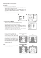
PREFACE .......................................................... 2 FEATURES ........................................................ 2 PRECAUTIONS ................................................. 2 MAJOR OPERATING CONTROLS AND THEIR FUNCTIONS ........................................... 3 SETUP PROCEDURE ........................................ 4 ■ Setup Menu ............................................... 4 ■ Setup Menu Description ............................ 7 ■ Setting Procedures .....................
PREFACE PRECAUTIONS Panasonic presents highly advanced CCVE technology to meet the demand of new and ever-changing applications. The WV-CS400 is unitized colour video surveillance device which features 1/3" CCD Digital Signal Processing (DSP) high performance camera, pan/tilt mechanism, 10 times zoom lens and receiver in its compact enclosure. The camera portion incorporates 1/3" high sensitive CCD and provides 480-line horizontal resolution and 48 dB of S/N ratio.
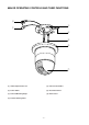
MAJOR OPERATING CONTROLS AND THEIR FUNCTIONS w e q r t y u (1) Video Output Connector (5) Fall Prevention Wire (2) Power Cable (6) Decoration Cover (3) Camera Mounting Angle (7) Dome Cover (4) Pan/Tilt Starting Point -3-
White Balance AWC ATW Manual Level Adjustment Manual Level Adjustment Manual Mask Area Selection Manual Mask Area Selection Auto-Pan On/Off Chroma Gain Special Menu Gain Pedestal -4- Camera Reset
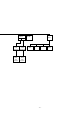
SETUP PROCEDURE ■ Setup Menu This camera utilizes a user setup menu that is displayed on-screen. This setup menu contains various sub menus with a Tree-Type structure as shown below. This menu is described in the "SETUP MENU DESCRIPTION". Camera ID Editing Light Control ALC MANUAL Camera ID Display Position Preset Off Setup Menu Shutter Speed ON/OFF AGC ON/OFF Manual Iris Adjustment Preset ON (Back Light Compensation) Sync.
• In Case of WV-RM70 Up Switch: Down Switch: Right Switch: Left Switch: Set Switch: Moves the cursor upwards. Moves the cursor downwards. Moves the cursor right. The mode is also selected by this switch and adjustment of certain levels can be made by this switch. Moves the cursor left. The mode is also selected by this switch and adjustment of certain levels can be made by this switch. The mode is set by this switch. Also, the menus can be changed by this switch.
■ Setup Menu Description ● Camera (1) Camera Identification (CAMERA ID) Up to 16 alpha/numeric characters for camera identification can be displayed near the bottom of the picture. The ID display ON or OFF mode is selected by the primary setup menu and the editing of displayed characters is performed in the associated sub menu. Note: Refer to the Camera Identification Setting for more details.
so much that all other objects in the scene appear dark. With the field setup mode for back light compensation, it is possible to mask out the spotlight and increase the rest of the scene's brightness as shown below. In addition to the mask area setup, the overall video output level can be adjusted by using the level adjustment (LEVEL) while in the preset "OFF" mode for both the ALC and ELC modes.
(6) Synchronization (SYNC) Important Notice: The priority of sync mode is as follows. 1. Multiplexed Vertical Drive (VD2) (Highest) 2. Line-lock (LL) 3. Internal Sync (INT) (Lowest) Note: The automatic sync mode selection is made according to priority listed above. Refer to the Synchronization Setting on page 14 for detailed procedures. (7) White Balance (WHITE BAL) A colour characteristic of illumination is called colour temperature and it is measured in units of Kelvin (°K).
(8) Special Menu (SPECIAL) Chroma level, aperture level, and pedestal level can be adjusted. Your settings can be released to return to the default settings. See page 18 for the setting method. * SPECIAL * CHROMA GAIN AP GAIN PEDESTAL CAMERA RESET ....I.... ....I.... .I....... − + →PUSH SW RET (9) Automatic Panning (AUTO PAN) Select one of the two panning modes below. OFF : Operates the panning manually AUTO PAN : Operates the panning automatically with the preset panning range.
■ CAMERA SETTING Setup menu 1. To display Camera Setting Menu ** SET UP ** 1. Move the cursor to CAMERA∗, and press the CAM (SET) button. The camera setting menu is displayed. CAMERA ID ALC/MANUAL SHUTTER AGC SYNC WHITE BAL AUTO PAN OFF * ALC * OFF ON INT ATW * OFF SPECIAL * 2. Camera Identification (CAMERA ID) Setting • Move the cursor to the "CAMERA ID" mode position, and select either "ON" (Camera identification characters are displayed) or "OFF" mode by using the Joystick.
• The display position of the camera ID on the monitor screen can be placed anywhere on the screen by using the Joystick. Notes: 1. The positioning of the camera ID stops at the edges of the monitor screen. 2. The camera ID moves faster when the Joystick is kept pressed for more than 0.5 seconds. ABCDEFGHIJKLM NOPQRSTUVWXYZ 0123456789 ().,'":;&#!?= +-*/%$ÄÜÖÆÑÅ ← → SPACE POSI RET RESET WV-CS400.......
(1)-1 ALC Mode with Preset Mode (PRESET ON) • Move the cursor to the "PRESET" mode position and select the "ON" mode by using the Joystick. The preset mode menu is displayed on the monitor screen as shown. • Move the cursor to "RET" position by using the Joystick and press the CAM (SET) Button to return to the Set Up menu.
(2) MANUAL Mode Move the cursor ALC/MANUAL position by using the Joystick and select the MANUAL by using the Joystick. The MANUAL menu is displayed. Control the level by using the Joystick. Manual setting menu * MANUAL CONT * IRIS ....I.... CLOSE OPEN RET Camera setting menu 5. Shutter Speed Setting (SHUTTER) • Display the Setup menu. • If necessary, refer to Setup Menu Display, for details on displaying the Setup menu on the monitor screen.
Line-lock Sync Mode (LL) • Display the Setup menu. • If necessary, refer to Setup Menu Display, for details on displaying the Setup menu on the monitor screen. • Move the cursor to the "SYNC" mode position and select the line-lock "LL" mode by using the Joystick. This setup can be only made when the multiplexed vertical drive (VD2) pulse is not supplied to the camera. • After confirming that the cursor is on the "LL" position, press the CAM (SET) Button on the rear panel.
Notes: 1. When the cursor "I" reaches to the end of "+" position, the cursor "I" jumps to the "−" position. At the same time, the step number of the "COARSE" mode increases one step to enable a continuous adjustment. The reverse operation takes place when the cursor "I" reaches to the end of "−" position. 2. When the Joystick is kept placing to right or left for more than one second, the cursor "I" moves quickly. 3.
(2) Automatic White Balance Control Mode (AWC) • Move the cursor to the "WHITE BAL" mode position and select the "AWC → PUSH SW" mode by using the Joystick. AWC fine adjustment menu * AWC * R • Press the CAM (SET) Button to activate the white balance setup. The "PUSH SW" display starts blinking to indicate that the white balance is being set. • When the white balance setting is completed, the blinking "PUSH SW" stops blinking. ....I.... − + ....I....
3. To set a panning start position and panning end position Follow the steps below. (1) Move the cursor to POSITION SET and press the CAM (SET) button. The cursor moves to START. ** AUTO PAN ** POSITION SET SPEED ENDLESS STOP TIME (2) Move the joystick to left or right to select a panning start position and press the CAM (SET) button. This determines the start position and the cursor moves to END. (3) Move the joystick to left or right to select a panning end position and press the CAM (SET) button.
(1) Chroma Level Setting (CHROMA GAIN) • Move the cursor to the "CHROMA GAIN" mode position. The cursor "I" starts blinking. • While observing the vectorscope or colour video monitor, adjust the chroma level by using the Joystick. The cursor "l" moves left or right. Special menu * SPECIAL * CHROMA GAIN AP GAIN PEDESTAL CAMERA RESET ....I.... ....I.... .I....... − + →PUSH SW RET (2) Aperture Level Setting (AP GAIN) • Move the cursor to the "AP GAIN" mode position. The cursor "l" starts blinking.
1. Remove the Mounting Screw (M3) from the Camera Mounting Angle (provided). 2. Mark the mounting holes into the ceiling by using the removed Camera Mounting Angle as a template. INSTALLATION Precautions : 1. The following all installations should be made by qualified service personnel or system installers and should confirm to all local codes. 2. Be sure to use the ceiling board having the enough strength to support this camera. 3.
6. Tighten the Mounting Screw (provided). Notes : 1. Tighten the Camera Fixing Screw with the screwdriver. 2. Do mount the camera and Camera Mounting Angle completely as shown in the following. 3. When removing the camera from the Camera Mounting Angle, loosen and press up the Camera Fixing Screw (M3) by using the screwdriver. 4. Hang the Fall Prevention Wire to the Camera Mounting Angle. Be sure to match the wire with the Fall Prevention Wire Fixing Angle as shown below. 7.
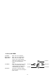
CONNECTIONS Precaution: The following connections should be made by qualified service personnel or system installers. 220 - 240V AC Video Output Cable Coaxial Cable (5C - 2V) BNC Plug BNC Plug To Video IN (CAMERA IN) ✻ Coaxial cable length should be less than 1200m (with 5C - 2V) Notes: • The self-check operation (The zooming and focusing are operated once) is done after turning on the power. • When the AUTO PAN ON mode has been selected, panning will start automatically.
SYSTEM CONNECTION Combination Camera Max.
PREVENTION OF BLOOMING AND SMEAR When the camera is aimed at a bright light, such as a spot light, or a surface that reflects bright light, smear or blooming may appear. Therefore, the camera should be operated carefully in the vicinity of extremely bright objects to avoid smear or blooming.
SPECIFICATIONS Combination Camera Power Source : Ambient Operating Temperature : Dimensions : Weight : 220 - 240V AC, 50Hz 12W −10°C - +50°C (14°F - 122°F) 130 (D) x 195 (H) mm 2 kg Camera Pick-up Device : Synchronization Horizontal Scanning Frequency : Vertical Scanning Frequency : Video Output : Horizontal Resolution : Vertical Resolution : Signal-to-noise : Minimum Illumination : Zoom Speed : Focus Speed : Iris : Maximum Aperture Ratio : Focal Length : Electronic Shutter : Back Light Compensation : Zoo
Matsushita Electric Industrial Co., Ltd. Central P.O.