
Information

ELECTRICAL SOLUTIONS
Order number of pieces required, in multiples of Standard Package Quantity.
Prime items appear in BOLD.
D1.50
B2.
Cable
Accessories
C1.
Wiring
Duct
C3.
Abrasion
Protection
C4.
Cable
Management
D1.
Terminals
D2.
Power
Connectors
E1.
Labeling
Systems
E2.
Labels
E3.
Pre-Printed
& Write-On
Markers
F.
Index
B3.
Stainless
Steel Ties
C2.
Surface
Raceway
E5.
Lockout/
Tagout
& Safety
Solutions
B1.
Cable Ties
A.
System
Overview
D3.
Grounding
Connectors
E4.
Permanent
Identification
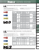
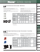
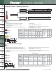
Right Angle Female Disconnect, Nylon Insulated – Funnel Entry
• Right angle design for use in limited space applications
• Disconnect can be inserted and removed from the male tab
without the use of tools for lower installed cost
• Longer barrel design for use with Panduit standard disconnect tool
• UL Flammability UL 94V-2/HB, maximum insulation temperature
221°F (105°C)
• UL and CSA rated up to 600 V per UL 310
**Bulk packaging may be available, contact Panduit Customer Service for additional information.
‡UL and CSA approved tooling/product combinations. For crimping tool information, see pages D1.84 and D1.88.
Type DNFR-B
W
H
D
L
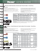
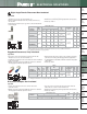
Right Angle Female Disconnect, Non-Insulated – Metal Sleeve
• Right angle design for use in limited space applications
• Disconnect can be inserted and removed from the male tab
without the use of tools for lower installed cost
• Sleeved barrel helps to facilitate high mechanical and electrical
performance when crimping
• Barrel of terminal internally beveled to provide quick and easy
wire insertion
• Internal barrel serrations assure good wire contact and maximum
tensile strength
• Maximum recommended operating temperature 302°F (150°C)
• UL and CSA rated up to 2000 V per UL 310
**Bulk packaging may be available, contact Panduit Customer Service for additional information.
‡UL and CSA approved tooling/product combinations. For crimping tool information, see pages D1.83, D1.84,
D1.86 and D1.88.
▲
UL Recognized only.
Type DR
Part Number
Wire
Range
Color
Code
Max.
Ins.
(In.)
Figure Dimensions
(In.)
Tab
Size
(In.)
Recommended
Installation
Tool
Std.
Pkg.
Qty.
Std.
Ctn.
Qty.
L W H D
DNFR18-205B-L
22 – 18
AWG
Red
0.130 0.78 0.36 0.20 0.62 0.205/0.187
x 0.032
CT-1525‡,
CT-2500‡
50 500
DNFR18-206B-L
0.130 0.78 0.36 0.20 0.62 0.205/0.187
x 0.020
50 500
DNFR18-250B-L
0.130 0.78 0.36 0.20 0.62 0.250
x 0.032
50 500
DNFR14-205B-L
16 – 14
AWG
Blue
0.155 0.78 0.36 0.20 0.63 0.205/0.187
x 0.032
CT-1525‡,
CT-2500‡
50 500
DNFR14-206B-L
0.155 0.78 0.36 0.20 0.63 0.205/0.187
x 0.020
50 500
DNFR14-250B-L
0.155 0.78 0.36 0.20 0.63 0.250
x 0.032
50 500
Part Number
Wire
Range
Figure Dimensions
(In.)
Tab
Size
(In.)
Recommended
Installation
Tool
Std.
Pkg.
Qty.
Std.
Ctn.
Qty.
L W H D
DR18-205-C
22 – 18
AWG
0.54 0.25 0.12 0.53 0.205/0.187 x 0.032
CT-100A‡,
CT-200‡,
CT-600-A‡,
CT-1570‡,
CT-2500‡
100 1000
DR18-206-C
0.54 0.25 0.12 0.53 0.205/0.187 x 0.020 100 1000
DR18-250-C
0.57 0.30 0.12 0.54 0.250 x 0.032 100 1000
DR14-205-C
16 – 14
AWG
0.54 0.25 0.12 0.55 0.205/0.187 x 0.032
CT-100A‡,
CT-200‡,
CT-600-A‡,
CT-1570‡,
CT-2500‡
100 1000
DR14-206-C
0.54 0.25 0.12 0.55 0.205/0.187 x 0.020 100 1000
▲
DR14-250-C
0.57 0.30 0.12 0.55 0.250 x 0.032 100 1000
DR10-250-L
12 – 10
AWG
0.61 0.30 0.12 0.57 0.250 x 0.032 CT-100A‡,
CT-200‡,
CT-600-A‡,
CT-1570‡,
CT-1701‡,
CT-2500‡
50 500