
Information

ELECTRICAL SOLUTIONS
Order number of pieces required, in multiples of Standard Package Quantity.
Prime items appear in BOLD.
D1.60
B2.
Cable
Accessories
C1.
Wiring
Duct
C3.
Abrasion
Protection
C4.
Cable
Management
D1.
Terminals
D2.
Power
Connectors
E1.
Labeling
Systems
E2.
Labels
E3.
Pre-Printed
& Write-On
Markers
F.
Index
B3.
Stainless
Steel Ties
C2.
Surface
Raceway
E5.
Lockout/
Tagout
& Safety
Solutions
B1.
Cable Ties
A.
System
Overview
D3.
Grounding
Connectors
E4.
Permanent
Identification
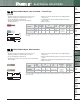
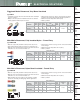
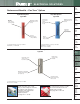
Male Metric Disconnect, Non-Insulated – Butted Seam
• Male tab couples with (all 6.3mm x 0.8mm) female disconnects
• Male tab can be inserted and removed from the female disconnect
without the use of tools for lower installed cost
• Internal barrel serrations assure good wire contact and maximum
tensile strength
• Barrel of terminal internally beveled to provide quick and easy
wire insertion
• Maximum recommended operating temperature 302°F (150°C)
• Rated up to 2000 V
*Brazed seam.
For crimping tool information, see pages D1.84 and D1.88.
Type DM-M
L
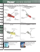
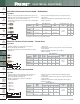
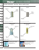
Metric Pin Terminal, Vinyl Insulated – Funnel Entry
• Solid pin designed to prevent damage to the wire from over
tightening, resulting in a reliable electrical connection
• For use with pin-type terminal blocks
• Insulation support helps to prevent wire damage in bending
applications
• Brazed seam protects terminal barrel from splitting during the
crimp process
• Internal barrel serrations assure good wire contact and maximum
tensile strength
• Maximum insulation temperature 221°F (105°C)
• Rated up to 600 V
For crimping tool information, see pages D1.84 and D1.88.
Type PMV-P
L
P
W
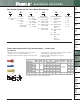
Metric Pin Terminal, Non-Insulated
• Solid pin designed to prevent damage to the wire from over
tightening, resulting in a reliable electrical connection
• For use with pin-type terminal blocks
• Insulation support helps to prevent wire damage in
bending applications
• Brazed seam protects terminal barrel from splitting during the
crimp process
• Internal barrel serrations assure good wire contact and maximum
tensile strength
• Maximum recommended operating temperature 302°F (150°C)
• Rated up to 2000 V
For crimping tool information, see pages D1.84 and D1.88.
Type PM-P
P
L
W
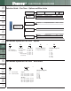
Part Number
Wire
Range
(mm
2
)
Figure Dimensions
(mm)
Tab
Size
(mm)
Recommended
Installation
Tool
Std.
Pkg.
Qty.
Std.
Ctn.
Qty.
L
DM1-63M-C
0.5 – 1.0 19.2 6.3 x 0.8
CT-1570,
CT-2500
100 500
DM2-63M-C
1.5 – 2.5 19.2 6.3 x 0.8 100 500
DM6-63M-L*
4.0 – 6.0 18.2 6.3 x 0.8 50 250
Part Number
Wire
Range
(mm
2
)
Figure Dimensions
(mm)
Recommended
Installation
Tool
Std.
Pkg.
Qty.
Std.
Ctn.
Qty.
L W P
PM1-P10-C
0.5 – 1.0 19.0 1.8 12.4
CT-1570,
CT-2500
100 500
PM2-P10-C
1.5 – 2.5 19.0 1.8 12.4 100 500
PM6-P10-L
4.0 – 6.0 20.1 2.8 14.0 50 250
Part Number
Wire
Range
(mm
2
)
Color
Code
Max.
Ins.
(mm)
Figure Dimensions
(mm)
Recommended
Installation
Tool
Std.
Pkg.
Qty.
Std.
Ctn.
Qty.
L W P
PMV1-P10-CY
0.5 – 1.0 Red 3.80 21.1 2.0 11.9
CT-1550,
CT-2500
100 500
PMV2-P10-C
1.5 – 2.5 Blue 4.30 21.1 2.0 11.9 100 500
PMV6-P10-L
4.0 – 6.0 Yellow 6.40 27.9 2.5 14.0 50 250