
Information

ELECTRICAL SOLUTIONS
D3.32
B2.
Cable
Accessories
C1.
Wiring
Duct
C3.
Abrasion
Protection
C4.
Cable
Management
D1.
Terminals
D2.
Power
Connectors
E1.
Labeling
Systems
E2.
Labels
E3.
Pre-Printed
& Write-On
Markers
F.
Index
B3.
Stainless
Steel Ties
C2.
Surface
Raceway
E5.
Lockout/
Tagout
& Safety
Solutions
B1.
Cable Ties
A.
System
Overview
D3.
Grounding
Connectors
E4.
Permanent
Identification
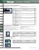
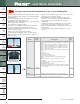
3. Select the proper crimping die and
crimping tool to be used with
the connector.
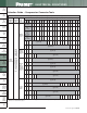
Use crimping tools and dies that provide a UL Listed
and/or CSA Certified electrical termination, to assure
a safe and reliable connection.
Many Panduit compression connectors are UL
Listed and CSA Certified when crimped with Panduit
and specified competitor crimping tools and dies.
These tools and dies are listed in the tool charts* in
this catalog. Panduit crimping tools and dies to be
used with each connector are also listed on the
installation instructions included with Panduit product
packaging.
Panduit compression connectors are
color-coded and marked with Panduit and
specified competitor die index numbers.
Select the proper crimping die to be used
by matching the color code and die index
number marked on the connector to the
same markings on the crimping die.
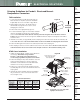
4. Crimp the connector.
Insert the conductor into the barrel of the connector.
The conductor should stop against the end of the
barrel of the lug, or wire stop in the butt splice, upon
complete insertion of the conductor in
the barrel. Some lugs are offered with
inspection windows that provide visual
inspection of the complete
conductor insertion.
Review the installation instructions included with the
Panduit product packaging or the tool charts* for the
proper number of crimps to be placed in the
connector. Make the first crimp in the barrel nearest
the tongue of the lug, or wire
stop in a butt
splice, and make
successive
crimps in the
barrel working
towards the
conductor entry at the end of
the barrel. Use the color-coded or knurled
band markings on the barrel of the
connector to evenly space the placement
of the crimps in the barrel.
When properly crimped, the die index
number engraved in the crimping die will be
embossed into the barrel of the connector.
The crimp should be placed in the connector
so the die index number can be easily read
when the connector is installed.
*See tool charts on pages D3.56 – D3.94.
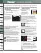
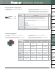
1. Select the proper Panduit compression
connector for the conductor type and
size being used.
• Panduit compression connectors are
identified with the proper conductor size and
conductor type marked on the tongue or
barrel of the connector
• The proper conductor
size and type to be used
with each connector can
also be found in the
installation instructions
included with Panduit
product packaging and
in the tool charts* in
this catalog
2. Strip the conductor to the proper strip
length. As specified:
• On the Panduit product
packaging label or
• On the installation instructions
included with Panduit
product packaging or
• In the tool charts* in
this catalog
Make sure the conductor is not stripped too long,
which would result in exposed wire between the
barrel of the connector and the cable insulation.
Make sure the conductor is not stripped too short,
which would result in a less than complete contact
area with the connector when the conductor is
inserted in the barrel.
Do not nick or cut strands of conductor during
crimping, which would result in a less than premium
conductor termination.
Make sure conductor strands are free
from corrosion.
Crimping Guidelines for Panduit
®
Pan-Lug
™
Compression Lugs and Splices
Identify