
Information

For technical assistance in the U.S., call 866-405-6654 (outside the U.S., see inside back cover for directory)
ELECTRICAL SOLUTIONS
D3.33
B2.
Cable
Accessories
C1.
Wiring
Duct
C3.
Abrasion
Protection
C4.
Cable
Management
D1.
Terminals
D2.
Power
Connectors
E1.
Labeling
Systems
E2.
Labels
E3.
Pre-Printed
& Write-On
Markers
F.
Index
B3.
Stainless
Steel Ties
C2.
Surface
Raceway
E5.
Lockout/
Tagout
& Safety
Solutions
B1.
Cable Ties
A.
System
Overview
D3.
Grounding
Connectors
E4.
Permanent
Identification
Crimping Guidelines for Panduit
®
StructuredGround
™
Compression Connectors
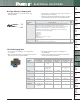
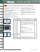
TAP Installation
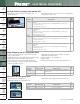
HTAP Cover Installation
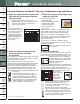
1. Locate desired position of TAP along main wire run.
Allow clearance for tap wires (and cover installation
if applicable). See clear cover table on page D3.13.
2. Strip insulation from wires to the length shown in
the TAP table on page D3.14. Use care to avoid
damaging the conductors.
3. Position wires in the appropriate tap grooves.
4. For easier installation, apply one of the flame retardant
cable ties (provided) around the wires and through the
slots in the TAP. The head of the cable tie
must
be positioned along the side of the TAP as shown in
Figure A. Tension and cut off excess length of tie. Additional cable ties may be used adjacent to the TAP to
secure the wires.
5. Install the correct dies (see page D3.94) into the crimping tool. Position the locator die into the stationary die
holder. Note: The color code and die index number shown on the HTAP and crimping dies
must
match.
6. Position the TAP against the locator in the stationary die holder of the crimping tool.
7. After crimping, if desired, cut off the cable tie head or remove the entire cable tie. Note: In some cases, the
cable tie head must be cut off in order for the crimped connector to fit inside the insulating cover.
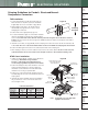
1. If labels are being utilized, cut labels to the dimensions
shown below. Note: When using a Panduit
®
Pan-Ther
™
LS8E printer, the length dimensions
can be easily programmed to provide cut-off marks.
2. Position the label(s) in the pockets inside the cover and
snap in the label retainer(s) as shown in Figure B.
Information can be marked on the matte finish label
retainers in lieu of using a separate label.
3. Position one cover half around the crimped connector
assembly. Align the second cover half with the first and
snap together.
4. Install the two flame retardant cable ties (provided) in
the grooved areas on the cover. Tension and cut off
excess lengths of ties.
Figure A
Figure B
Cover allows for a clear
view of the label and
label protection
Non-adhesive
label may
be used
Two label
retainers provided
Pockets for
cable tie heads
Guides for
cable ties
Write-on surface
on label retainer
Label
pockets provided
Guides for
cable ties
Crimping
Direction
Note: Configuration of cover may differ
slightly from illustration.
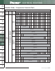
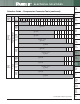
Clear Cover
Part Number
CLRCVR1-1
CLRCVR2-1
CLRCVR3-1
.38 1.56 1.00
.38 1.87 1.25
.38 2.37 1.75
Label Height
(Max.)
Label Length
(Wrap-Around
Style)
Label Length
(Flat Style)
Label Size Information