
Information


ELECTRICAL SOLUTIONS
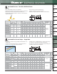
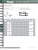
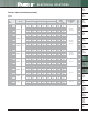
Order number of pieces required, in multiples of Standard Package Quantity.
Prime items appear in BOLD.
D1.82
B2.
Cable
Accessories
C1.
Wiring
Duct
C3.
Abrasion
Protection
C4.
Cable
Management
D1.
Terminals
D2.
Power
Connectors
E1.
Labeling
Systems
E2.
Labels
E3.
Pre-Printed
& Write-On
Markers
F.
Index
B3.
Stainless
Steel Ties
C2.
Surface
Raceway
E5.
Lockout/
Tagout
& Safety
Solutions
B1.
Cable Ties
A.
System
Overview
D3.
Grounding
Connectors
E4.
Permanent
Identification
Crimping Guidelines for Panduit
®
Pan-Term
®
Terminals, Disconnects,
Splices and Wire Joints (continued)
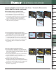
Insulated and Non-Insulated Wire Joints
A. Properly strip wires per manufacturer’s
recommendations on product package label.
B. Twist stripped wire ends together and insert wires into
wire joint.
C. Locate wire joint in appropriate wire gauge crimp die
pocket and position crimp in the center of the
metal insert.
D. Squeeze tool handles firmly to perform the electrical
crimp.
(See Note 2 below)
Note: An insulation crimp is not required on an insulated
wire joint.
NOTES for Crimping with the Preferred Hand Operated Controlled Cycle Crimping Tools:
1. Panduit controlled cycle crimping tools properly locate rings, forks, and barrel insulated disconnects, pins, and blades. No
further positioning is required.
2. When using the preferred controlled cycle tool, once a crimp has been started, the ratchet device of controlled cycle
tools will not release until the crimp is complete, independent of operator expertise.
3. Controlled cycle tools provide the electrical crimp and the insulation closure in a single cycle of the tool.
4. When using controlled cycle tooling, insulated butt splices must be inserted from the back of the tool to ensure that the
electrical and insulation closure crimp pockets are properly aligned with the splice.
Steps A and B Steps C and D
Complete Crimp
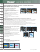
5. Perform the electrical crimp using the preferred
controlled cycle tool
A. Make sure the terminal barrel is centered correctly in the
right die pocket by using the product locator on the
backside of the tool.
B. Determine the correct die pocket to use based on the color
code of the terminal.
C. Squeeze the handles of the tool until one click is heard;
this click indicates the terminal is now held in place
securely to insert the wire.
D. Insert the wire and complete cycle to perform the electrical
and insulation crimp simultaneously.
E. Crimp is complete.
Step A Step B Step C
Complete Crimp
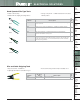
6. Inspect the crimp
Note: If your crimp looks like any of the examples shown
below, cut off the terminal and re-crimp. These crimps
would provide a poor connection!
Bent Back Strands Over Crimp
Rotated Crimp
Step D