
Information

ELECTRICAL SOLUTIONS
Order number of pieces required, in multiples of Standard Package Quantity.
Prime items appear in BOLD.
D2.90
B2.
Cable
Accessories
C1.
Wiring
Duct
C3.
Abrasion
Protection
C4.
Cable
Management
D1.
Terminals
D2.
Power
Connectors
E1.
Labeling
Systems
E2.
Labels
E3.
Pre-Printed
& Write-On
Markers
F.
Index
B3.
Stainless
Steel Ties
C2.
Surface
Raceway
E5.
Lockout/
Tagout
& Safety
Solutions
B1.
Cable Ties
A.
System
Overview
D3.
Grounding
Connectors
E4.
Permanent
Identification
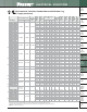
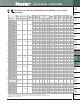
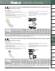
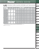
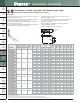
Flex Conductor, Two-Hole, Long Barrel with Window Lug
• Can be used with code conductor and flex conductor class: G, H, I,
K, M and Diesel Locomotive
• Long barrel maximizes number of crimps and provides premium
wire pull-out strength and electrical performance
• Generously beveled wire entry prevents bent back strands when
inserting conductor into barrel
• Color-coded barrels marked with Panduit and specified competitor
die index numbers for proper crimp die selection
• Inspection window to visually assure full conductor insertion
• Tin-plated to inhibit corrosion
• UL Listed and CSA Certified to 35 KV** and temperature rated to
90°C when crimped with Panduit and specified competitor
crimping tools and dies
• Meets J-STD-607-A and TIA-942 requirements for network
systems grounding applications
• Available with NEMA hole sizes and spacing
For Use with Flexible, Extra-Flexible, and Code Stranded Copper Conductors
Type LCCX
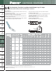
‡See pages D3.70 – D3.73 for tool and die information.
*Not UL Listed or CSA Certified with Class K flex conductor when crimped with Burndy tools.
**Consult cable manufacturer for voltage stress relief instructions with applications greater than 2000 V.
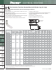
^Slotted lug, refer to Figure 2.
◆NEMA hole sizes and spacing.
W
HOLE
SPACING
L
INSPECTION
WINDOW
T
B
W
HOLE
SPACING
T
L
INSPECTION
WINDOW
B
Figure 1
Figure 2: Slotted
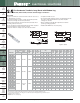
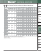
Part Number
Flex Conductor Size
Code
Conductor
Size
Stud
Hole
Size
(In.)
Stud
Hole
Spacing
(In.)
Figure Dimensions
(In.)
Panduit
Color
Code
Panduit
Die
Index
No.‡
Burndy
Die
Index
No.‡
T&B
Die
Index
No.‡
Wire
Strip
Length
(In.)
Std.
Pkg.
Qty.
Class
G, H, I, K, M
Diesel
Locomotive
W B T L
LCCX8-10A-L
#8 AWG #8 AWG #8 AWG
#10 0.63 0.41 0.70 0.08 2.01 Red P21 49 21 3/4 50
LCCX8-10B-L
#10 0.75 0.41 0.70 0.08 2.14 Red P21 49 21 3/4 50
LCCX8-10AB-L^
#10 0.63 – 0.75 0.41 0.70 0.08 2.14 Red P21 49 21 3/4 50
LCCX8-14A-L
1/4 0.63 0.48 0.70 0.07 2.10 Red P21 49 21 3/4 50
LCCX8-14B-L
1/4 0.75 0.48 0.70 0.07 2.23 Red P21 49 21 3/4 50
LCCX8-14AB-L^
1/4 0.63 – 0.75 0.48 0.70 0.07 2.23 Red P21 49 21 3/4 50
LCCX8-14D-L
1/4 1.00 0.48 0.70 0.07 2.48 Red P21 49 21 3/4 50
LCCX8-38D-L
3/8 1.00 0.60 0.70 0.05 2.70 Red P21 49 21 3/4 50
LCCX6-10B-L
#6 AWG #6 AWG #6 AWG
#10 0.75 0.46 1.07 0.08 2.52 Blue P24 7 24 1 1/8 50
LCCX6-14A-L
1/4 0.63 0.48 1.07 0.08 2.49 Blue P24 7 24 1 1/8 50
LCCX6-14B-L
1/4 0.75 0.48 1.07 0.08 2.61 Blue P24 7 24 1 1/8 50
LCCX6-14AB-L^
1/4 0.63 – 0.75 0.48 1.07 0.08 2.61 Blue P24 7 24 1 1/8 50
LCCX6-14D-L
1/4 1.00 0.48 1.07 0.08 2.86 Blue P24 7 24 1 1/8 50
LCCX6-38A-L
3/8 0.63 0.62 1.07 0.06 2.71 Blue P24 7 24 1 1/8 50
LCCX6-38C-L
3/8 0.88 0.62 1.07 0.06 2.96 Blue P24 7 24 1 1/8 50
LCCX6-38AC-L^
3/8 0.63 – 0.88 0.62 1.07 0.06 2.96 Blue P24 7 24 1 1/8 50
LCCX6-38D-L
3/8 1.00 0.62 1.07 0.06 3.08 Blue P24 7 24 1 1/8 50
LCCX4-14A-L
#4 AWG
#5, #4, #3
AWG
#4 AWG
1/4 0.63 0.55 1.05 0.09 2.49 Gray
P29
8 29 1 1/8 50
LCCX4-14B-L
1/4 0.75 0.55 1.05 0.09 2.63 Gray P29 8 29 1 1/8 50
LCCX4-14AB-L^
1/4 0.63 – 0.75 0.55 1.05 0.09 2.63 Gray P29 8 29 1 1/8 50
LCCX4-14CE-L^
1/4 0.88 – 1.25 0.55 1.05 0.09 3.12 Gray P29 8 29 1 1/8 50
LCCX4-38B-L
3/8 0.75 0.62 1.05 0.08 2.84 Gray P29 8 29 1 1/8 50
LCCX4-38D-L
3/8 1.00 0.62 1.05 0.08 3.09 Gray P29 8 29 1 1/8 50
LCCX4-38BD-L^
3/8 0.75 – 1.00 0.62 1.05 0.08 3.09 Gray P29 8 29 1 1/8 50