
Information


For technical assistance in the U.S., call 866-405-6654 (outside the U.S., see inside back cover for directory)
ELECTRICAL SOLUTIONS
D1.27
B2.
Cable
Accessories
C1.
Wiring
Duct
C3.
Abrasion
Protection
C4.
Cable
Management
D1.
Terminals
D2.
Power
Connectors
E1.
Labeling
Systems
E2.
Labels
E3.
Pre-Printed
& Write-On
Markers
F.
Index
B3.
Stainless
Steel Ties
C2.
Surface
Raceway
E5.
Lockout/
Tagout
& Safety
Solutions
B1.
Cable Ties
A.
System
Overview
D3.
Grounding
Connectors
E4.
Permanent
Identification
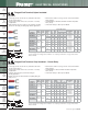
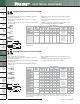
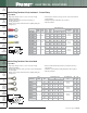
Short Locking Fork Terminal, Nylon Insulated – Funnel Entry
• Locks in place for a secure connection in limited spaces
• Fork design provides for fast and easy installation, without the
need to remove fastener
• Metal insulation grip sleeve crimps to wire insulation, providing
protection to the crimp joint during high vibration applications
• Internal barrel serrations assure good wire contact and maximum
tensile strength
• UL Flammability UL 94V-2/HB, maximum insulation temperature
221°F (105°C)
• UL and CSA rated up to 600 V per UL 486A/B
**Bulk packaging may be available, contact Panduit Customer Service for additional information.
For crimping tool information, see pages D1.84 and D1.88.
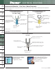
Type PNF-SLF
C
L
W
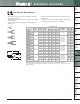
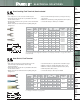
Short Locking Fork Terminal, Vinyl Insulated – Funnel Entry
• Locks in place for a secure connection in limited spaces
• Fork design provides for fast and easy installation, without the
need to remove fastener
• Insulation support helps to prevent wire damage in
bending applications
• Internal barrel serrations assure good wire contact and maximum
tensile strength
• UL Flammability UL 94V-0, maximum insulation temperature
221°F (105°C)
• UL and CSA rated up to 600 V per UL 486A/B
*Not UL Listed or CSA Certified.
**Bulk packaging may be available, contact Panduit Customer Service for additional information.
For crimping tool information, see pages D1.84 and D1.88.
^CSA Certified only.
C
L
W
Type PV-SLF
Part Number
Wire
Range
Color
Code
Stock
Thickness
(In.)
Max.
Ins.
(In.)
Stud
Size
Figure Dimensions
(In.)
Recommended
Installation
Tool
Std.
Pkg.
Qty.**
Std.
Ctn.
Qty.
L W C
PNF18-5SLF-C
22 – 18
AWG
Red
0.03 0.145 #5 0.75 0.26 0.19
CT-1550,
CT-1551,
CT-2500
100 500
PNF18-6SLF-C
0.03 0.145 #6 0.75 0.27 0.19 100 500
PNF18-8SLF-C
0.03 0.145 #8 0.80 0.29 0.23 100 500
PNF18-10SLF-C
0.03 0.145 #10 0.81 0.33 0.23 100 500
PNF14-5SLF-C
16 – 14
AWG
Blue
0.03 0.162 #5 0.75 0.25 0.19
CT-1550,
CT-1551,
CT-2500
100 500
PNF14-6SLF-C
0.03 0.162 #6 0.75 0.25 0.19 100 500
PNF14-8SLF-C
0.03 0.162 #8 0.82 0.29 0.23 100 500
PNF14-10SLF-C
0.03 0.162 #10 0.81 0.33 0.23 100 500
PNF14-14SLF-C
0.03 0.162 1/4" 0.91 0.44 0.28 100 500
PNF10-6SLF-L
12 – 10
AWG
Yellow
0.04 0.225 #6 0.91 0.25 0.17
CT-1550,
CT-1551,
CT-2500
50 500
PNF10-8SLF-L
0.04 0.225 #8 0.92 0.29 0.22 50 500
PNF10-10SLF-L
0.04 0.225 #10 0.93 0.33 0.22 50 500
PNF10-14SLF-L
0.04 0.225 1/4" 1.02 0.45 0.28 50 500
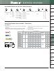
Part Number
Wire
Range
Color
Code
Stock
Thickness
(In.)
Max.
Ins.
(In.)
Stud
Size
Figure Dimensions
(In.)
Recommended
Installation
Tool
Std.
Pkg.
Qty.**
Std.
Ctn.
Qty.
L W C
PV18-5SLF-CY^
22 – 18
AWG
Red
0.03 0.150 #5 0.82 0.26 0.19
CT-1550,
CT-1551,
CT-2500
100 500
PV18-6SLF-CY^
0.03 0.150 #6 0.82 0.27 0.19 100 500
PV18-8SLF-CY^
0.03 0.150 #8 0.87 0.29 0.23 100 500
PV18-10SLF-CY^
0.03 0.150 #10 0.88 0.33 0.23 100 500
PV14-5SLF-C*
16 – 14
AWG
Blue
0.03 0.175 #5 0.80 0.25 0.22
CT-1550,
CT-1551,
CT-2500
100 1000
PV14-6SLF-C*
0.03 0.175 #6 0.80 0.25 0.22 100 1000
PV14-8SLF-C*
0.03 0.175 #8 0.85 0.29 0.26 100 1000
PV14-10SLF-C*
0.03 0.175 #10 0.86 0.33 0.26 100 1000
PV14-14SLF-C*
0.03 0.175 1/4" 0.95 0.44 0.33 100 1000
PV10-5SLF-L
12 – 10
AWG
Yellow
0.04 0.225 #5 0.86 0.25 0.22
CT-1550,
CT-1551,
CT-2500
50 500
PV10-6SLF-L
0.04 0.225 #6 0.87 0.25 0.22 50 500
PV10-8SLF-L
0.04 0.225 #8 0.92 0.29 0.26 50 500
PV10-10SLF-L
0.04 0.225 #10 0.92 0.33 0.26 50 500
PV10-14SLF-L
0.04 0.225 1/4" 1.02 0.45 0.33 50 500