
Information


For technical assistance in the U.S., call 866-405-6654 (outside the U.S., see inside back cover for directory)
ELECTRICAL SOLUTIONS
D1.31
B2.
Cable
Accessories
C1.
Wiring
Duct
C3.
Abrasion
Protection
C4.
Cable
Management
D1.
Terminals
D2.
Power
Connectors
E1.
Labeling
Systems
E2.
Labels
E3.
Pre-Printed
& Write-On
Markers
F.
Index
B3.
Stainless
Steel Ties
C2.
Surface
Raceway
E5.
Lockout/
Tagout
& Safety
Solutions
B1.
Cable Ties
A.
System
Overview
D3.
Grounding
Connectors
E4.
Permanent
Identification
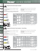
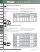
• Locks in place for a secure connection in limited spaces
• Fork design provides for fast and easy installation, without the
need to remove fastener
• Internal barrel serrations assure good wire contact and maximum
tensile strength
• Brazed seam protects terminal barrel from splitting during the
crimp process
• Barrel of terminal internally beveled to provide quick and easy
wire insertion
• Maximum recommended operating temperature 302°F (150°C)
• UL and CSA rated up to 2000 V per UL 486A/B
**Bulk packaging may be available, contact Panduit Customer Service for additional information.
‡UL and CSA approved tooling/product combinations. For crimping tool information, see pages D1.83, D1.84,
D1.86 and D1.88.
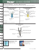
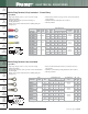
Short Locking Fork Terminal, Non-Insulated
C
L
W
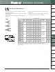
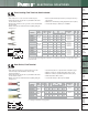
Heat Shrink, Fork Terminal
• Heat shrink sleeving forms a protective barrier to provide
environmentally sealed terminations ideal for high
moisture applications
• Fork design provides for fast and easy installation, without the
need to remove fastener
• Brazed seam protects terminal barrel from splitting during the
crimp process
• Heat shrink insulation is completed with a standard heat gun
• Minimum continuous operating temperature -65°F (-55°C)
• Maximum continuous operation temperature 230°F (110°C)
• Shrink temperature 300°F (150°C)
• UL and CSA rated up to 600 V per UL 486A/B
For crimping tool information, see page D1.85.
Type PH-F
L
W
Type P-SLF
Part Number
Wire
Range
Stock
Thickness
(In.)
Stud
Size
Figure Dimensions
(In.)
Recommended
Installation
Tool
Std.
Pkg.
Qty.**
Std.
Ctn.
Qty.
L W C
P18-6SLF-C
22 – 16
AWG
0.03 #6 0.51 0.27 0.22
CT-100A‡,
CT-200‡,
CT-600-A‡,
CT-1570‡,
CT-2500‡
100 1000
P18-8SLF-C
0.03 #8 0.56 0.29 0.25 100 1000
P18-10SLF-C
0.03 #10 0.57 0.33 0.25 100 1000
P14-6SLF-C
16 – 14
AWG
0.03 #6 0.51 0.25 0.22
CT-100A‡,
CT-200‡,
CT-600-A‡,
CT-1570‡,
CT-2500‡
100 1000
P14-8SLF-C
0.03 #8 0.56 0.29 0.25 100 1000
P14-10SLF-C
0.03 #10 0.57 0.33 0.25 100 1000
P14-14SLF-C
0.03 1/4" 0.66 0.44 0.35 100 1000
P10-5SLF-L
14 – 10
AWG
0.04 #5 0.60 0.25 0.19
CT-100A‡,
CT-200‡,
CT-600-A‡,
CT-1570‡,
CT-1701‡,
CT-2500‡
50 500
P10-8SLF-L
0.04 #8 0.66 0.29 0.23 50 500
P10-10SLF-L
0.04 #10 0.67 0.33 0.23 50 500
P10-14SLF-L
0.04 1/4" 0.76 0.45 0.28 50 500
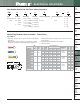
Part Number
Wire
Range
Color
Code
Max.
Ins.
(In.)
Stud
Size
Figure Dimensions
(In.)
Wire
Strip
Length
Recommended
Installation
Tool
Std.
Pkg.
Qty.
Std.
Ctn.
Qty.
L W
PH18-6F-Q
22 – 18
AWG
Red
0.170 #6 1.04 0.32 5/16
CT-310
25 125
PH18-8F-Q
0.170 #8 1.04 0.32 5/16 25 125
PH18-10F-Q
0.170 #10 1.04 0.32 5/16 25 125
PH14-6F-Q
16 – 14
AWG
Blue
0.190 #6 1.07 0.38 5/16
CT-310
25 125
PH14-8F-Q
0.190 #8 1.07 0.38 5/16 25 125
PH14-10F-Q
0.190 #10 1.07 0.38 5/16 25 125
PH10-8F-E
12 – 10
AWG
Yellow
0.240 #8 1.20 0.38 5/16
CT-310
20 100
PH10-10F-E
0.240 #10 1.20 0.38 5/16 20 100