
Information


For technical assistance in the U.S., call 866-405-6654 (outside the U.S., see inside back cover for directory)
ELECTRICAL SOLUTIONS
D2.53
B2.
Cable
Accessories
C1.
Wiring
Duct
C3.
Abrasion
Protection
C4.
Cable
Management
D1.
Terminals
D2.
Power
Connectors
E1.
Labeling
Systems
E2.
Labels
E3.
Pre-Printed
& Write-On
Markers
F.
Index
B3.
Stainless
Steel Ties
C2.
Surface
Raceway
E5.
Lockout/
Tagout
& Safety
Solutions
B1.
Cable Ties
A.
System
Overview
D3.
Grounding
Connectors
E4.
Permanent
Identification
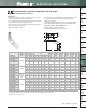
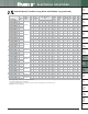
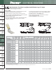
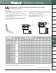
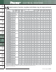
Code Conductor, Two-Hole, Long Barrel with Window Lug, 90° Angle
• Long barrel maximizes number of crimps and provides premium
wire pull-out strength and electrical performance
• Inspection window to visually assure full conductor insertion
• Color-coded barrels marked with Panduit and specified competitor
die index numbers for proper crimp die selection
• Tin-plated to inhibit corrosion
• UL Listed and CSA Certified to 35 KV** and temperature rated
to 90°C when crimped with Panduit and specified competitor
crimping tools and dies
• UL Listed and CSA Certified for wide wire range-taking capability
when crimped with Panduit
®
Uni-Die
™
Dieless Crimping Tools‡
• Tested by Telcordia – meets NEBS Level 3
• Meets J-STD-607-A and TIA-942 requirements for network
systems grounding applications
• Available with NEMA hole sizes and spacing
INSPECTION
WINDOW
W
HOLE
SPACING
B
L
90°
T
For Use with Stranded Copper Conductors
Type LCC-WF
B
INSPECTION
WINDOW
HOLE
SPACING
W
L
90°
T
Figure 1
Figure 2: Slotted
‡See pages D3.62 – D3.65 for tool and die information.
*Not tested to NEBS Level 3 requirements.
**Consult cable manufacturer for voltage stress relief instructions with applications greater than 2000 V.
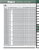
Table continues on pages D2.54 — D2.55
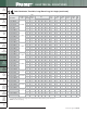
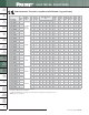
Part Number
Figure
No.
Copper
Conductor
Size
Stud
Hole
Size
(In.)
Stud
Hole
Spacing
(In.)
Figure Dimensions
(In.)
Panduit
Color
Code
Panduit
Die Index
No.‡
Burndy
Die Index
No.‡
T&B
Die Index
No.‡
Wire Strip
Length
(In.)
Std.
Pkg.
Qty.
W B T L
LCC10-14JAWF-L*
2
#14 – #10
AWG
STR, #12
–#10
AWG SOL
1/4 0.50 – 0.63 0.42 0.53 0.05 1.56 ————9/16 50
LCC10-14AWF-L*
1 1/4 0.63 0.42 0.53 0.05 1.56 ————9/16 50
LCC10-14BWF-L*
1 1/4 0.75 0.42 0.53 0.05 1.69 ————9/16 50
LCC8-10AWF-L
1
#8 AWG
#10 0.63 0.41 0.70 0.08 1.53 Red P21 49 21 3/4 50
LCC8-10BWF-L
1 #10 0.75 0.41 0.70 0.08 1.65 Red P21 49 21 3/4 50
LCC8-14AWF-L
1 1/4 0.63 0.48 0.70 0.07 1.61 Red P21 49 21 3/4 50
LCC8-14BWF-L
1 1/4 0.75 0.48 0.70 0.07 1.74 Red P21 49 21 3/4 50
LCC8-14DWF-L
1 1/4 1.00 0.48 0.70 0.07 1.99 Red P21 49 21 3/4 50
LCC8-38DWF-L
1 3/8 1.00 0.60 0.70 0.05 2.21 Red P21 49 21 3/4 50
LCC6-10AWF-L
1
#6 AWG
#10 0.63 0.46 1.07 0.08 1.57 Blue P24 7 24 1 1/8 50
LCC6-10BWF-L
1 #10 0.75 0.46 1.07 0.08 1.69 Blue P24 7 24 1 1/8 50
LCC6-14JWF-L
1 1/4 0.50 0.48 1.07 0.08 1.53 Blue P24 7 24 1 1/8 50
LCC6-14AWF-L
1 1/4 0.63 0.48 1.07 0.08 1.66 Blue P24 7 24 1 1/8 50
LCC6-14JAWF-L
2 1/4 0.50 – 0.63 0.48 1.07 0.08 1.66 Blue P24 7 24 1 1/8 50
LCC6-14BWF-L
1 1/4 0.75 0.48 1.07 0.08 1.78 Blue P24 7 24 1 1/8 50
LCC6-14DWF-L
1 1/4 1.00 0.48 1.07 0.08 2.03 Blue P24 7 24 1 1/8 50
LCC6-14EWF-L
1 1/4 1.25 0.48 1.07 0.08 2.28 Blue P24 7 24 1 1/8 50
LCC6-56BWF-L
1 5/16 0.75 0.56 1.07 0.07 1.90 Blue P24 7 24 1 1/8 50
LCC6-38BWF-L
1 3/8 0.75 0.62 1.07 0.06 2.00 Blue P24 7 24 1 1/8 50
LCC6-38CWF-L
1 3/8 0.88 0.62 1.07 0.06 2.13 Blue P24 7 24 1 1/8 50
LCC6-38DWF-L
1 3/8 1.00 0.62 1.07 0.06 2.25 Blue P24 7 24 1 1/8 50