DPoE™ Power Patch Panel User’s Guide Part Numbers: DPOE24U1X, DPOE24U1XY, DPOE12U1X, DPOE12U1XY, DPOE24S1X, DPOE24S1XY Issue 2.2 Part Number: PN378A August 2006 © 2006 PANDUIT Corp. All Rights reserved www.panduit.
PANDUIT® DPoE™ Power Patch Panel User’s Guide Issue 2.2 Part Number: PN378A Safety Warning Always observe standard safety precautions during installation, operation and maintenance of this product. Read the installation instructions before you connect the unit to its power source. This unit must be connected to earth ground, do not bypass the grounding system. To avoid the possibility of electric shock, disconnect the power cord from the power source before removing the cover or performing any repairs.
PANDUIT® DPoE™ Power Patch Panel User’s Guide Issue 2.2 Part Number: PN378A TABLE OF CONTENTS Safety Warning................................................................................................................. i WARRANTY..................................................................................................................... i TRADEMARKS ................................................................................................................ i OVERVIEW........................
PANDUIT® DPoE™ Power Patch Panel User’s Guide Issue 2.2 Part Number: PN378A Refresh the Network........................................................................................... 43 Administering E-mail Settings............................................................................. 43 Search for Specific Panel(s) or Port(s) ............................................................... 45 EM Log Messages........................................................................................
PANDUIT® DPoE™ Power Patch Panel User’s Guide Issue 2.2 Part Number: PN378A Table 14: Package Contents ......................................................................................... 53 Table 15: PANDUIT Corp Contact Information.............................................................. 54 Table 16: Color-Coded Wire Positions for 802.3af-2003 Compliant Devices ................ 57 Table 17: Color-Coded Wire Positions for Alternate PoE Devices ................................
PANDUIT® DPoE™ Power Patch Panel User’s Guide Issue 2.2 Part Number: PN378A OVERVIEW The DPoE™ Power Patch Panel provides a reliable and cost-effective solution for Power over Ethernet (PoE) applications, complaint with the IEEE 802.3af-2003 specifications. Each DPoE™ Power Patch Panel allows centralized powering of up to 24 devices, such as Internet Protocol-based (IP) telephones, Network Security Cameras, or Wireless Devices, over the same cabling used to provide the Ethernet connectivity.
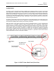
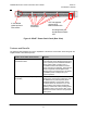
PANDUIT® DPoE™ Power Patch Panel User’s Guide A- and B-feed (optional) Power Connections Issue 2.2 Part Number: PN378A OUT management port and OUT Network Status LED Punchdown connections IN management port and IN Network Status LED Figure 2: DPoE™ Power Patch Panel (Rear View) Features and Benefits The following table highlights some of the capabilities of the DPoE™ Power Patch Panel along with the tangible benefit to the network operator.
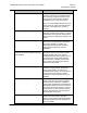
PANDUIT® DPoE™ Power Patch Panel User’s Guide Issue 2.2 Part Number: PN378A DPoE™ Power Patch Panel Feature Benefit IEEE 802.3af-2003 Compliant Many currently available in-line PoE powering options are not standards-based, thus requiring coordination between each device’s power needs and the technical capabilities of the in-line powering unit. Any port on the PANDUIT® DPoE™ Power Patch Panel can support the 802.3af-2003 standard or the legacy Cisco powering scheme.
PANDUIT® DPoE™ Power Patch Panel User’s Guide Issue 2.2 Part Number: PN378A DPoE™ Power Patch Panel Feature Benefit Easier Installation By eliminating the need for separate midspan patch panels and the associated need for patch cord, in a network-ready 1RU high package, The DPoE™ Power Patch Panel is fast and easy to install.
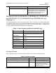
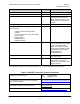
PANDUIT® DPoE™ Power Patch Panel User’s Guide Item Issue 2.2 Part Number: PN378A Quantity Notes Quick Installation Instructions 1 PANDUIT Part Number PN370 DPOE™ Installation Worksheet 1 PANDUIT Part Number PN377 Metric and English screws 12 Installation requires six screws. One bag of six metric screws (M6x1.0x16) and one bag of six English screws (12-24x1/2”) are included.
PANDUIT® DPoE™ Power Patch Panel User’s Guide IMPORTANT: Issue 2.2 Part Number: PN378A The DPOE™ Installation Worksheet should be used to record pertinent information when installing DPoE™ Power Patch Panel(s), particularly if the EM is monitoring the network. (See page 29, Provisioning the Panel, for more information on how this information will be entered in the EM.) The installer should complete this worksheet.
PANDUIT® DPoE™ Power Patch Panel User’s Guide Issue 2.2 Part Number: PN378A Grounding Requirements Network Connection 5. If the Element Manager is not being used to remotely manage the network of DPoE™ Power Patch Panels, skip to Connecting the Powered Devices below. Otherwise, using a standard patch cord (for example, PANDUIT part number UTPCH3 or UTPSP3), connect the IN management port on the back of the panel to an Ethernet switch.
PANDUIT® DPoE™ Power Patch Panel User’s Guide Issue 2.2 Part Number: PN378A 8. Fan out all four twisted pairs in the specified wiring sequence (see color-coded wiring positions in Table 4: Color-Coded Wire Positions for 802.3af-2003 Compliant Devices and Table 5: Color-Coded Wire Positions for Alternate PoE Devices below). The colors are also displayed on the Wiring Template Label, already installed on the back of the DPoE™ Power Patch Panel.
PANDUIT® DPoE™ Power Patch Panel User’s Guide Issue 2.2 Part Number: PN378A 9. Lay conductors into the punchdown slots for the specified port using the correct wiring sequence. Cable jacket removal should be minimized to the extent possible. Conductor untwist should be within ½” (12.7 mm) of termination. WARNING: NEVER TOUCH UNINSULATED COMMUNICATIONS WIRING OR TERMINALS UNLESS THE COMMUNICATION LINE HAS BEEN DISCONNECTED AT THE NETWORK INTERFACE.
PANDUIT® DPoE™ Power Patch Panel User’s Guide WARNING: Issue 2.2 Part Number: PN378A The power supply connections are polarized. The DPoE™ Power Panel will not function if power is wired improperly. For Maximum power the overall length of the wire between the power supply and the DPoE™ Power Panel must not exceed 35 feet. NOTE: The included power harness has two wires for the A-feed power only (pins 1 & 2).
PANDUIT® DPoE™ Power Patch Panel User’s Guide Issue 2.2 Part Number: PN378A Table 6: DPoE™ Power Patch Panel Power Up Sequence Behavior as viewed from the back of the unit Behavior as viewed from the front of the unit Both network status LEDs will light amber for two seconds The panel status Light-Emitting Diode (LED) will light red for about 10 seconds. After that, a LED test sequence of the port status LEDs will take place, lighting each port status LED amber.
PANDUIT® DPoE™ Power Patch Panel User’s Guide Issue 2.2 Part Number: PN378A Table 7: Basic Troubleshooting Guide Problem Possible Causes and Solutions The panel status LED does not light when power is applied to the unit. 1. The power supply fuse may be blown. Check the fuse on the DPoE™ Power Patch Panel power supply. 2. The power connection may be bad. Check the physical connection and make sure the voltage polarity is proper. 3. No power is available at the panel.
PANDUIT® DPoE™ Power Patch Panel User’s Guide Issue 2.2 Part Number: PN378A OPERATION LED Indicators The DPoE™ Power Patch Panel displays system and port status through the use of LEDs on the front and rear of each panel. There is one panel status LED on the front left of the panel, 24 individual port status LEDs above each port, and twonetwork status LEDs on the rear of the unit. These LEDs enable the technician to see at a glance if either the ports or the panel itself is in alarm.
PANDUIT® DPoE™ Power Patch Panel User’s Guide LED Color Port LED Status Red Solid Issue 2.2 Part Number: PN378A Description Status of Power Ports The system has failed to determine the PD power requirements for this port. Perhaps this PD is not an 802.3af-2003 compliant or Cisco legacy power device. It could also be a port configured for 802.3af2003 and an alternate PoE device has been connected. Power is NOT being delivered down this port on the panel.
PANDUIT® DPoE™ Power Patch Panel User’s Guide Issue 2.2 Part Number: PN378A ELEMENT MANAGER SOFTWARE The optional PANDUIT® Element Manager is used to remotely control, configure and monitor the DPoE™ Power Patch Panels within the network. Once installed on a shared or dedicated Windows-based Personal Computer (PC), the EM can be used to manage an entire network of DPoE™ Power Patch Panels. The PANDUIT® Element Manager is shipped on a CD-ROM included with the DPoE™ Power Patch Panel.
PANDUIT® DPoE™ Power Patch Panel User’s Guide Display Settings Issue 2.2 Part Number: PN378A For XP Professional or Home Edition: Settings: 1024x768 or larger Color Quality: Medium (16-bit) or higher Advanced: Normal Size Fonts (96dpi) REQUIRED Appearance: Font Size Normal REQUIRED For Windows 2000: 1024x768x32K colors Small Fonts REQUIRED (Normal 96dpi) NOTE: If Microsoft .NET Framework version 1.
PANDUIT® DPoE™ Power Patch Panel User’s Guide Issue 2.2 Part Number: PN378A For security purposes, the network operator will then be given the opportunity to restrict the Element Manager to the administrator UserName only (default) or whether other users of this PC can access it. Once this selection is made, the installation process completes in only a few minutes. Remove the CD-ROM from the CD-ROM drive and store it in a safe place.
PANDUIT® DPoE™ Power Patch Panel User’s Guide Issue 2.2 Part Number: PN378A Panel, the PC must either be setup as a DHCP Server or the panel but be setup for a static IP address. If the PC is connected to the DPoE™ Power Patch Panel through an Ethernet network, the network must have a DHCP Server on it or the panel must be setup for a static IP address.
PANDUIT® DPoE™ Power Patch Panel User’s Guide Issue 2.2 Part Number: PN378A Some of the screen shots in this section may look different on the PC running the EM. The updated EM presents a slightly different look to the screen shots. In some cases, additional features have been added (refer to the same sections in the DPoE™ 8 Port Power Hub User’s Guide for more details on the added features).
PANDUIT® DPoE™ Power Patch Panel User’s Guide Issue 2.2 Part Number: PN378A The Tree View of the Network area provides a hierarchical display of each patch panel within the network using the configurable names assigned by the network operator. Multiple patch panels physically wired into a single rack are grouped on the screen under the configurable name of that rack.
PANDUIT® DPoE™ Power Patch Panel User’s Guide Issue 2.2 Part Number: PN378A By clicking on the Add button, the network operator can create new UserNames and Passwords for use the system. A free-form Description field is also available. Maintenance of UserNames is done by first clicking an existing Username, then clicking on either the Remove button to delete that UserName or the Properties button to have the following screen appear.
PANDUIT® DPoE™ Power Patch Panel User’s Guide NOTE: Issue 2.2 Part Number: PN378A A user cannot delete a currently active UserName. Panel Discovery Once the EM is connected into the network, the Discover capability can be used to "find" the deployed DPoE™ Power Patch Panels. (See page 21, Connecting the EM Host Computer to the DPoE™ Power Patch Panel, for more information.) The EM initiates messages into the control network and requests responses from any panels that see this message.
PANDUIT® DPoE™ Power Patch Panel User’s Guide Issue 2.2 Part Number: PN378A The network operator can set the Discover capability to search a specific subnetwork for panels or search across a range of IP addresses. The two leftmost buttons on this Discover Devices window are used to select which type of Discover to initiate. By selecting the top button, the top half of the screen is then used to request a subnetwork search.
PANDUIT® DPoE™ Power Patch Panel User’s Guide IMPORTANT: Issue 2.2 Part Number: PN378A The SNMP Community fields are case-sensitive and allow SNMP messages to be exchanged between the EM and the DPoE™ Power Patch Panels. FOR SECURITY REASONS, THESE FIELDS SHOULD BE CHANGED FROM THEIR DEFAULTS. Once any subnetwork changes are entered (if necessary), check ( searched and click the Start button.
PANDUIT® DPoE™ Power Patch Panel User’s Guide Issue 2.2 Part Number: PN378A Whether a subnetwork search or an IP range search was conducted, the discovered DPoE™ Power Patch Panel information will be populated in the Element Manager. TIP: In addition to the Discover capability, the Element Manager also supports a Refresh capability, which collects the information stored in each Patch Panel and verifies it’s consistent with the information in the EM.
PANDUIT® DPoE™ Power Patch Panel User’s Guide Issue 2.2 Part Number: PN378A 5. The table contains the MAC and IP address of the all of the panels. The message log will include the MAC and IP address of the newly discovered panel(s). The MAC Address can now be used to associate the discovered panel with the information contained on the installation worksheet, and the Panel Attributes can now be entered. 6. Double-click on the row in the table containing the first newly discovered panel.
PANDUIT® DPoE™ Power Patch Panel User’s Guide Issue 2.2 Part Number: PN378A The panel name, rack name, rack space position, and contact name should be entered here as shown above. The Element Manager will create a rack with that name, and any panel that has the same rack name will be grouped under that rack. This screen also includes a place to record the name and location information of the power system for this DPoE™ Power Patch Panel.
PANDUIT® DPoE™ Power Patch Panel User’s Guide Issue 2.2 Part Number: PN378A 8. Once all of the information is entered, click the Save button and this information will be saved to the panel and the graphic for the rack will be shown in the Element Manager Tree View of the Network area along with a graphical representation of the panel with the proper name. (See page 23, Figure 3: System-Level Opening Screen, for more information.) 9.
PANDUIT® DPoE™ Power Patch Panel User’s Guide Issue 2.2 Part Number: PN378A Administering Port and Panel-level Information The PANDUIT® Element Manager makes it easy to administer the deployed network of DPoE™ Power Patch Panels. When a specific panel is selected in the Tree Level View of the Network on the systemlevel opening screen, the EM automatically retrieves the latest power and LED information from the selected panel and displays on the View Panel Screen.
PANDUIT® DPoE™ Power Patch Panel User’s Guide Issue 2.2 Part Number: PN378A Figure 5: Edit Panel Screen TIP: Prior to modifying any entries on this screen, click on the Refresh button to retrieve the latest information stored in the specific panel. This screen will allow the network operator to change the panel IP address, the panel attributes, the SNMP setting, or the trap settings.
PANDUIT® DPoE™ Power Patch Panel User’s Guide Issue 2.2 Part Number: PN378A panels wired in a single rack will be displayed consistent with the value in the Rack Space Position field. (See page 29, Provisioning the Panel, for more information.) Once these values are set in the EM, this information will be transmitted and stored in the DPoE™ Power Patch Panels. Two additional fields are available on this screen and affect the operation of the panel.
PANDUIT® DPoE™ Power Patch Panel User’s Guide Issue 2.2 Part Number: PN378A Copy/Paste/Delete Panel Information The EM also provides a unique feature that will allows the network operator to more efficiently configure the network by allowing all panel-level information to be copied from one panel to another. The Copy Panel and Paste Panel options under the Tools pull-down menu provide an easy mechanism to perform this task.
PANDUIT® DPoE™ Power Patch Panel User’s Guide Issue 2.2 Part Number: PN378A If the Refresh Data option is checked, the EM will retrieve the latest information from the selected panels and before prompting the network operator to enter a filename and location where the information can be stored on the PC. After the panel-level information is saved, the operator is prompted as to whether port-level information should be stored in a separate file.
PANDUIT® DPoE™ Power Patch Panel User’s Guide Issue 2.2 Part Number: PN378A Port information for all ports on the selected panel. Tool bar Figure 6: View All Ports Screen − Edit Port Information Clicking any row on the port information section of this screen will bring up the configuration information for that individual port. This is the same screen that will appear by double-clicking an individual port on the Visual Display of the Front Panel portion on the View Panel Screen.
PANDUIT® DPoE™ Power Patch Panel User’s Guide Issue 2.2 Part Number: PN378A Curent port configuration plus EDIT button Messages logged for this port Tool Bar Figure 7: View Individual Port Screen Clicking on the Edit button will bring up the screen to edit individual ports on a DPoE™ Power Patch Panel.
PANDUIT® DPoE™ Power Patch Panel User’s Guide Issue 2.2 Part Number: PN378A If the network operator were simultaneously configuring multiple ports, the following screen would instead appear and any values not overwritten would be left unchanged. Administration Control - This setting {on/off} allows the network operator to control whether each individual port is sourcing PoE power. If this field is set to off, the port acts like any port on a non-powered patch panel rather than a PoE port.
PANDUIT® DPoE™ Power Patch Panel User’s Guide Issue 2.2 Part Number: PN378A View Entire Log The View Entire Log button on the tool bar on the View Panel Screen can be used to perform this task. Viewing the message logs can also be activated from most points within the EM using the button on the top tool bar.
PANDUIT® DPoE™ Power Patch Panel User’s Guide Issue 2.2 Part Number: PN378A The View Message Log area provides a sequential listing of all messages received by the EM, displaying them in a first-in, first-out manner. That is, the most recently received messages are listed at the top of the window and the older messages are pushed down toward the bottom of the window.
PANDUIT® DPoE™ Power Patch Panel User’s Guide − Issue 2.2 Part Number: PN378A Clear Log By clicking on the Clear Log button, the operator will be given the opportunity to export the log before erasing the entire log. NOTE: Clearing the log will clear the entire message log in the EM. It cannot be used to selectively clear a portion of the log.
PANDUIT® DPoE™ Power Patch Panel User’s Guide NOTE: Issue 2.2 Part Number: PN378A Before any e-mail messages can be sent from the system, the SMTP Server and Source E-mail Address fields must be entered. The Source E-mail Address will be used as the "from" address on all e-mails sent from the Element Manager. Once this information is added, check the E-mail Enabled box and store the settings using the Save button.
PANDUIT® DPoE™ Power Patch Panel User’s Guide Issue 2.2 Part Number: PN378A Once the e-mail addresses are entered into the system and a specific e-mail address is selected on the left panel of the E-mail Settings, the right panel is used to select which message categories will be sent to that e-mail address. (See page 47, EM Log Messages, for more information on each of these message types.) NOTE: The same category of events may be selected for multiple destination e-mail addresses.
PANDUIT® DPoE™ Power Patch Panel User’s Guide Tabs Panel level searches can be conducted by any combination of: - MAC address, - Panel Name, - Rack Name, - Rack Space Location - Hardware Version, - IP Address, - Physical Location, - Power Supply Location, - Firmware Version. 46 Issue 2.
PANDUIT® DPoE™ Power Patch Panel User’s Guide Issue 2.2 Part Number: PN378A Port level searches can be conducted by any combination of: - Port Number, - PD Type, - Work Area Location - Administration Control, - Detection Status, - Power Priority, - Power Classification, - Legacy Control. EM Log Messages The following types of messages are generated within the DPoE™ Power Patch Panel network and are displayed in the EM logs.
PANDUIT® DPoE™ Power Patch Panel User’s Guide Message Category Priority Level Issue 2.2 Part Number: PN378A Description Panel Agent – Cold Start Advisory The main software process (i.e., the panel agent) in a previously known panel is now up and running. The process likely reset itself New Panel Discovered Advisory The Discover capability has found a new panel. PD Connected Minor A new Powered Device has been detected at the panel. PD Disconnected Minor A Powered Device has been disconnected.
PANDUIT® DPoE™ Power Patch Panel User’s Guide Issue 2.2 Part Number: PN378A If the Online indicator is not checked ( ), the EM assumes it is in the offline mode and will not attempt to connect to the deployed Patch Panel Network. Changes made within the EM will not be updated in the panels.
PANDUIT® DPoE™ Power Patch Panel User’s Guide NOTE: Issue 2.2 Part Number: PN378A An important feature of the DPoE™ Power Patch Panel is its ability to continue supplying Power over Ethernet during firmware updates. All IEEE 802.3af and Cisco In-Line protocol legacy powered devices connected to the Panel will remain powered during a firmware update. Cisco In-Line protocol legacy new powered device detection may experience an interruption during a firmware update.
PANDUIT® DPoE™ Power Patch Panel User’s Guide Issue 2.2 Part Number: PN378A 4. Enter the TFTP information in the EM screen and then click on the Begin Update button. 5. Observe the System status LED begins flashing red on the DPoE™ Power Patch Panel. See Table 12A: DPoE™ Power Patch Panel Firmware Update LED status for the LED activity during the Firmware update. 6. Allow sufficient time for the Firmware Update to complete. (Approximately 10 minutes) 7.
PANDUIT® DPoE™ Power Patch Panel User’s Guide System LED Color and activity Red rapid Blink Network LED Color and activity Green Blink Red slow Blink Red Solid Green Slow Blink Issue 2.2 Part Number: PN378A State Description Elapsed Time Image transfer and update in progress CRC code Image update complete Application Running 5 - 7 minutes Exiting the PANDUIT® Element Manager The Exit option under the File pull-down menu or the button ( 52 ) will exit the EM.
PANDUIT® DPoE™ Power Patch Panel User’s Guide Issue 2.2 Part Number: PN378A APPENDIX 1 – DPOE24S1X AND DPOE24S1XY INSTALLATION The PANDUIT® DPoE™ Shielded Power Patch Panel requires a direct connection to a nominal 48VDC supply. An individual power supply may be purchased separately from PANDUIT Corp or other vendors. Installation instructions for the individual power supply are included with that product. PANDUIT Corp provides multiple individual power supply options as listed below.
PANDUIT® DPoE™ Power Patch Panel User’s Guide Item Issue 2.2 Part Number: PN378A Quantity Notes Metric and English screws 13 Installation requires six screws. One bag of six metric screws (M6x1.0x16), one bag of six English screws (12-24x1/2”), and an additional screw for the rear shield are included. 8 inch grounding strap 1 Used to ground the panel to the frame. DPoE™ Power Patch Panel Support Tools CDROM containing: - PANDUIT Element Manager (EM) software.
PANDUIT® DPoE™ Power Patch Panel User’s Guide IMPORTANT: Issue 2.2 Part Number: PN378A The DPOE™ Power Patch Panel Installation Worksheet should be used to record pertinent information when installing DPoE™ Power Patch Panel(s), particularly if the PANDUIT® Element Manager is monitoring the network. (See page 29, Provisioning the Panel, for more information on how this information will be entered in the EM.) The installer should complete this worksheet.
PANDUIT® DPoE™ Power Patch Panel User’s Guide Issue 2.2 Part Number: PN378A 4. Record the rack space position on the Installation Worksheet. 5. Prepare the shielded cables for termination using the figures appropriate for the type of cable used. Caution: Do not damage conductors. To ensure the highest shielding effectiveness, cut 1.5” (38.1 mm) of copper tape, included in 4 strips inside the Power Patch Panel Installation Kit, and wrap it around the cable foil or braid.
PANDUIT® DPoE™ Power Patch Panel User’s Guide NOTE: Issue 2.2 Part Number: PN378A The DPoE™ Power Patch Panel can terminate most 22-24 AWG solid or stranded IWC wire with a .050” (1.27mm) max o.d. either PVC or Plenum rated. Table 17: Color-Coded Wire Positions for 802.
PANDUIT® DPoE™ Power Patch Panel User’s Guide Issue 2.2 Part Number: PN378A Networking The Panels (Optional) 8. If the Element Manager is not being used to remotely manage the network of DPoE™ Power Patch Panels, skip to Power Requirements. Otherwise, using a standard patch cord (for example, PANDUIT part number UTPCH3 or UTPSP3), connect the IN management port on the back of the panel to an Ethernet switch.
PANDUIT® DPoE™ Power Patch Panel User’s Guide Issue 2.2 Part Number: PN378A Power Requirements 10.
PANDUIT® DPoE™ Power Patch Panel User’s Guide Issue 2.2 Part Number: PN378A 15. Attach the top and bottom rear shields to the panel using the tabs on the shields. Be sure that the compliant conductive foam on the shields is in contact with the copper tape applied to the cables. Close the shields together over the cables and secure with PAN-TY's (PANDUIT part no. PLT1.5IM). Fasten the shields together using US standard screws with the grounding strap in-between the screw and the shields. 16.
PANDUIT® DPoE™ Power Patch Panel User’s Guide Issue 2.2 Part Number: PN378A Powering Up the DPoE™ Power Patch Panel 17. Apply power the panel. Once power is applied to the unit, the DPoE™ Power Patch Panel will go through its power up sequence. The following table describes the behavior of the unit as viewed from the front and the back.
PANDUIT® DPoE™ Power Patch Panel User’s Guide Issue 2.2 Part Number: PN378A TECHNICAL SPECIFICATIONS Dimensions: 24 port 1.72”H x 19.0”W x 5.08”D (43.7mm x 482.6mm x 129.0mm) 1RU Input Voltage Range: 46VDC to 57VDC Typical per port power output IEEE 802.3af-2003 compliant power, 16.1 watts/port (46VOUTDC @ 350mA) Maximum overall power consumption 490 Watts (57VINDC @ 8.
PANDUIT® DPoE™ Power Patch Panel User’s Guide GLOSSARY AWG American Wire Gauge DHCP Dynamic Host Configuration Protocol EM Element Manager IEEE Institute of Electrical and Electronic Engineers IP Internet Protocol LED Light-Emitting Diode MAC Media Access Control MHz Megahertz NMS Network Management System o.d.