
Submittal


©2008 PANDUIT Corp. All rights reserved. www.panduit.com 4
Fiber Systems:
Polarity Best Practices
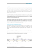
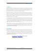
Male
Array
Connector
Female
Array
Connector
Array
Adapter
Pins
Key Up
No Pins
Key Down
White Dot
White
Dot
Key Up
Pin Location
Fiber Position
1
12
Figure 3. Array Connector Schematic (left) and End View (right)
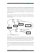
Cassettes. A cassette is a packaged, pre-terminated cabling assembly that transitions from small form factor
ribbon-style fiber cables and array connectors to traditional single-fiber connectors (see Figure 4). The primary
function of cassettes is to provide quick, scalable plug-in network deployment of up to 12 fiber ports (24 fibers)
in a single assembly to support high-density applications. Array adapters at the rear of cassettes are also keyed
to ensure proper orientation with keyed array connectors.
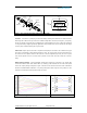
Patch Cords. Duplex patch cords used to complete serial duplex pair connections are available in two types
(see Figure 5), depending on which polarity technique is used. The “A-to-B” patch cord connects position A on
one end of the cord to position B on the other end; this is termed “straight-through” wiring. The “A-to-A” patch
cord connects position A on one end of the cord to position A on the other end, and is known as “crossover”
wiring.
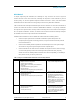
Ribbon Cable Assemblies. Factory-assembled modular fiber cassettes are connected to one another with
connectorized ribbon cables. Each 12-fiber ribbon (or “trunking”) cable translates into six 2-fiber serial optical
circuits that require polarity management. Figure 6 shows the three fiber-and-connector trunk combinations
described in TIA/EIA-568-B.1 Addendum 7 for polarity management when using fiber array cables; the chart
indicates the transformation of fiber position along each circuit.
Figure 4. Fiber Arrangement in Cassette
Figure 5. A-to-A and A-to-B Patch Cords