
Technical Bulletin
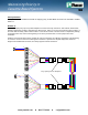
Table Of Contents

Maintaining Polarity I
n
Cassette-Based Systems
TECHNICAL REFERENCE
TR39
Purpose
Optical fiber links typically require two fibers to make a complete circuit. Optical transceivers have a transmit side
and receive side, and typically employee a duplex fiber connector as the interface. In any installation, it is
important to ensure that the optical transmitter at one end is connected to the optical receiver at the other. This
matching of the transmit signal (Tx) to the receive equipment (Rx) at both ends of the fiber optic link is referred to
as polarity. For traditional cabling systems using single fiber connectors, such as LC or SC, maintaining polarity is
as simple as insuring that the A side of one connector pair matches to the B side of the other connector pair in
any patch cord or permanent link. This procedure is well documented in the TIA/EIA-568-B.1 standard.
Pre-terminated, high-density cabling systems based on MTP*/MPO array connectivity require a new set of design
rules and have their own requirements for maintaining proper polarity. In this document, three different methods
for maintaining polarity in pre-terminated MTP* systems are reviewed. These three methods are defined by
TIA/EIA-568-B.1-7. The methods define installation and polarity management practices, and provide guidance in
the deployment of these types of fiber array links. Once a method is chosen, these practices must be put into
place to insure proper signaling throughout the installation.
MTP*/MPO Array Connectors
As a single fiber connector terminates 1 fiber per connector, array connectors terminate multiple fibers in a single
high-density interface. 12-fiber array connectors are the most common, though 4-, 6- and 8-fiber connectors are
also available. Array connectors are employed in high-density permanent link installations and can be found in
pre-terminated cassettes, trunk and hydra cable assemblies used extensively in data centers. Cassettes and
hydra cable assemblies transition the high-density cabling on the permanent link of the installation to the single
fiber connectors required by the transceivers in the switches.
Array connectors, shown in Figure 1, are pin and socket connectors -- requiring a male side and a female side.
Cassettes and hydra cable assemblies are typically manufactured with a Male (pinned) connector. Trunk cable
assemblies typically support a Female (unpinned) connector. The connectors are also keyed to ensure that
proper endface orientation occurs during the mating process. Generally, when looking at the endface of the
connector with the key is in the “up” position, Fiber 1 is the far left fiber on the same side as the white dot on the
connector, shown in Figure 2.
Figure 1 – 12-Fiber MTP* Male and Female Connectors Figure 2 – MTP* Connector Fiber Positions Relative to Key
Male
Array
Connector
Female
Array
Connecto
r
Array
Adapter
Pins
Key Up
No Pins
Key Down
White Dot
White
Dot
Key Up
Pin Location
Fiber Position
1
12
www.panduit.com y 800-777-3300 y cs@panduit.com