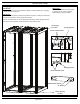
NET-SERV Cabinets INSTRUCTIONS CM408F © Panduit Corp. 2009-2011 FOR TECHNICAL SUPPORT www.panduit.com/resources/install_maintain.
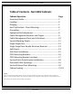
INSTRUCTIONS CM408F Table of Contents Ͳ NetͲSERV Cabinets Cabinet Operation Accessory Guide .. ... Leveling . ... Ganging .. AntiͲTip Brackets Ͳ Floor Mounting .. Grounding . Equipment Rail Adjustment Cable Management Brackets and Fingers Cable Management Panel and LͲRetainers Vertical Blanking Panels Single Hinge Door Single Hinge Door Handle Direction Reversal Split Doors Side Panel Installation .
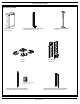
INSTRUCTIONS CM408F Accessory Guide Cabinet Side Panel (S22PS, S52PS) Cage Nut Equipment Rails and Brackets (S62RC, S65RC, S72RC, S75RC) Casters (SCSTR) Vertical Patch Panel Bracket (SVPPB) POU Brackets (SVPDUB) [6] L-Fingers and [1] CMSRC2 are included per panel Cable Management Finger Bracket and Fingers (S62BRFK, S65BRFK, S72BRFK, S75BRFK) Cable Management Panel and L-Retainers (S62BRCK, S65BRCK, S72BRCK, S75BRCK) For Technical Support: www.panduit.com/resources/install_maintain.
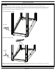
INSTRUCTIONS CM408F Leveling With the leveling legs fully retracted, use two people to slide the cabinet into the desired location. Lower the leveling legs using a 3/8” (10mm) deep well socket, until the cabinet weight is fully supported. Use a bubble level placed on the base rails in the locations shown to adjust legs until the cabinet is level.
INSTRUCTIONS CM408F Ganging IMPORTANT: If side panels are going to be used between cabinets, install (if needed) prior to ganging cabinets as shown on page 15. IMPORTANT: Ensure tops of cabinets are touching prior to ganging. Do not cinch the cabinets together with the ganging hardware. IMPORTANT: Ensure cabinets are level by following the guidelines on page 4. Leveling the cabinet prior to ganging is important to ensure proper door operation.
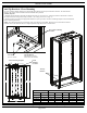
INSTRUCTIONS CM408F Anti-Tip Brackets - Floor Mounting NET-SERV Cabinets, whether stand alone or ganged with other cabinets, must always be anchored to the floor. The frame anchors directly to the concrete slab or threaded rod via the included anti-tip brackets. Assembly Sequence 1. Install the anti-tip brackets to the inside of cabinet frame, using (2) 5/16” bolts (1/2” socket) per bracket as shown below. Brackets are slotted to allow for raising and lowering of cabinet.
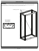
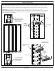
INSTRUCTIONS CM408F Grounding The grounding locations for connection to the CBN (Common Bonding Network) are shown below. Remove masking from desired grounding location (see detail below). Attach grouding lug with (2) #12-24 screws. Grounding jumpers are pre-installed between cabinet frame and rear split doors and are included in all NET-SERV configurations that ship with split doors installed on cabinet.
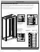
INSTRUCTIONS CM408F Equipment Rail Adjustment Loosen (2) 5/16” bolts at top of equipment rail bracket and (2) 5/16” bolts at bottom of equipment rail bracket to release clamping pressure to allow for front to back rail adjustment. Reposition rails and tighten (4) 5/16” bolts to 14ft.-lbs (19.0 N-m).
INSTRUCTIONS CM408F Cable Management Brackets and Fingers For precise positioning adjustment of cable management brackets, loosen (2) #12-24 hex head screws at top of bracket and (2) #12-24 hex head screws at bottom of bracket using 5/16” socket. Adjust bracket position and retighten (4) #12-24 hex head screws. For large adjustments, remove (4) #12-24 screws securing bracket to cabinet frame, reposition bracket, and secure cable management bracket with (4) #12-24 hex head screws as shown.
INSTRUCTIONS CM408F Cable Management Panel and L-Retainers For precise adjustment of cable management channel, loosen (2) #12-24 hex head screws at top of channel and (2) #12-24 hex head screws at bottom of channel using 5/16” socket. Adjust channel position and retighten (4) #12-24 hex head screws. For large adjustments, remove (4) #12-24 screws securing channel to cabinet frame, reposition channel, and secure cable management channel with (4) #12-24 hex head screws as shown.
INSTRUCTIONS CM408F Vertical Blanking Panels Bottom blanking panel is shipped uninstalled. To install, remove [1] #10 Phillips screw and [1] #10 lockwasher from each side at bottom of vertical blanking panels. Position bottom blanking panel over base frame of cabinet and secure with #10 Phillips screws and lockwashers as shown below. To adjust depth of vertical blanking panels, loosen (6) #10 Phillips screws on each vertical panel, adjust panels to desired depth and retighten (12) #10 Phillips screws.
INSTRUCTIONS CM408F Single Hinge Door Lift door into place and align lower hinge pin with lower door mounting bracket. Align upper hinge pin with upper door mounting bracket. Position door into place and pull down the lever of the spring loaded hinge pin and release lever when door is aligned. Reverse steps to remove the door. Note: Make sure that both pins are fully engaged when door is installed.
INSTRUCTIONS CM408F Single Hinge Door Handle Direction Reversal NOTE: NET-SERV cabinet configurations that ship with Single Hinge Doors are hinged on the left side by default. With single hinge door removed, remove (2) hinge brackets from cabinet frame by removing (2) #10 Phillips screws and (2) #10 lockwashers from each bracket and slide bracket out of cabinet frame as shown.
INSTRUCTIONS CM408F Split Doors To remove split doors, first disconnect grounding jumper between each door and cabinet frame (grounding jumpers are located near bottom of doors. Close split doors and remove (4) hinge pins (hinges include a safety feature that keeps doors captive unless they are open to 90 ). Open each split door to 90 and slide door away from cabinet and out of hinges. Reverse steps to reinstall split doors.
INSTRUCTIONS CM408F Side Panel Installation Lift up the side panel at an angle to the cabinet frame and align bottom of the panel to fit between the vertical posts of cabinet frame. Lower the side panel until the mounting hook is seated on the bottom side panel bracket and the panel is resting on the cabinet frame. Rotate the side panel into place until the panel is flush with the cabinet frame and the (2) latches engage.
INSTRUCTIONS CM408F POU Mounting Brackets For precise positioning of POU mounting brackets, loosen (2) #12-24 hex head screws at top bracket and (2) #12-24 hex head screws at bottom bracket using 5/16” socket. Adjust bracket positions and retighten (4) #12-24 hex head screws. For large adjustments, remove (2) #12-24 screws securing each bracket to cabinet frame, reposition brackets, and secure each bracket to cabinet frame with (2) #12-24 hex head screws.
INSTRUCTIONS CM408F POU Mounting Bracket Locations MAX 1 RU [1.75] MIN MAX For Technical Support: www.panduit.com/resources/install_maintain.
INSTRUCTIONS CM408F Vertical Patch Panel Bracket Installation Position vertical support of vertical patch panel bracket so that it nestles behind flange of finger bracket. Mounting points are located on the outside of finger bracket. Secure vertical patch panel bracket to Net-SERV finger bracket with (2) #12-24 hex head screws into tapped holes of vertical support of vertical patch panel as shown.
INSTRUCTIONS CM408F Overhead Cable Openings Cabinet is equipped with multiple covers and knockouts for cable entry. The bezel inserts can be removed from overhead cable opening bezels by pulling inserts out of position. Bezels can be removed from cabinet top by depressing tabs and pulling out of position. The remaining knockouts can be removed by cutting the (8) tabs with a wire cutter as shown. Additional bezels and bezel inserts are available for purchase.
INSTRUCTIONS CM408F Vertical Exhaust Duct Mounting NOTE: For ease of installation, a minimum of (2) persons are suggested for this assembly step. Lift exhaust duct assembly and position on top of cabinet as shown. Align large top flange towards front of cabinet. Secure duct to cabinet with (6) #10 x 1/2” Phillips trilobular screws and (6) #10 lockwashers as shown. Vertical Exhaust Duct is adjustable to allow for tight fit against ceiling.
INSTRUCTIONS CM408F Cabinet Sealing Adjacent cabinets may be ganged in one of the following conditions (see leveling and ganging instructions on pages 4-5): CABINET WITH NO SIDE PANEL adjacent to CABINET WITH NO SIDE PANEL - Bulb seals of adjacent cabinets firmly contact each other. Use ganging brackets to maintain firm contact of bulb seals (see page 5).
INSTRUCTIONS CM408F Cabinet Sealing Raise cabinet frame at least 1” above floor using leveling legs (see page 4). Install Front and Rear Floor Seal Brackets with foam seals to cabinet with (2) #10-32 x 1/2” Phillips trilobular screws and paint piercing washers per bracket. Foam seals are to sit under the cabinet frame when installed. Lower and level the cabinet frame to between 1/2” and 1” above floor to maintain a firm seal between cabinet frame and floor.
INSTRUCTIONS CM408F Cabinet Sealing Single Hinge Door Handle Reversal Door Catch Blanking Panels must be adjusted if Single Hinge Door Handle direction is to be reversed from default orientation (see page 13). Remove #6 Phillips counter-sink screw to adjust Door Catch Blanking Panels. Reposition blanking panels (maneuver blanking panels around rubber door bumper) as described below. Secure blanking panels in new position with #6 Phillips counter-sink screw.
INSTRUCTIONS CM408F THIS PAGE IS LEFT BLANK INTENTIONALLY For Instructions in Local Languages and Technical Support: www.panduit.com/resources/install_maintain.asp www.panduit.com Page 24 of 24 E-mail: cs@panduit.