CM599L STOP READ ALL OF THE FOLLOWING INSTRUCTIONS BEFORE REMOVING CABINET FROM SKID NET-ACCESS S-Type Server Cabinets TOOL LIST -Phillips screwdriver -Flatblade screwdriver -22mm socket wrench -15mm socket wrench -13mm socket wrench -8mm socket wrench -48” level -7mm socket wrench -T30 Torx bit -T25 Torx bit -6mm Allen key -2.
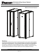
NET-ACCESS S-Type Server Cabinets (Server Configurations) © Panduit Corp. 2016 INSTALLATION INSTRUCTIONS CM599L NOTE: Some views in this document may vary slightly from your actual cabinet configuration. Disclaimer: The information contained in this manual is intended as a guide for use by persons having technical skill at their own discretion and risk. The recommended practices are based on average conditions.
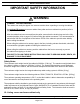
© Panduit Corp. 2016 INSTALLATION INSTRUCTIONS CM599L IMPORTANT SAFETY INFORMATION WARNING CABINET TIPPING HAZARD This cabinet can easily be tipped. Use extreme caution when unpacking or moving the cabinet. Use at least [2] persons to remove cabinet from pallet and move cabinet into position (refer to page 5). After the cabinet has been removed from the pallet, ensure that the leveling legs are in the fullyretracted position (refer to pages 5-6) before rolling the cabinet on casters.
© Panduit Corp. 2016 INSTALLATION INSTRUCTIONS TABLE OF CONTENTS-NET ACCESS S-TYPE SERVER CABINETS General Cabinet Operation Packaging Material Removal ......................................................................................................... 5 Leveling.......................................................................................................................................... 6 Floor Mounting ......................................................................................
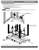
© Panduit Corp. 2016 INSTALLATION INSTRUCTIONS CM599L Packaging Material Removal “Shipping Hold Down Bracket” Doubles as Floor Mounting Bracket. Retain bracket if floor mounting is desired.
© Panduit Corp.
© Panduit Corp. 2016 INSTALLATION INSTRUCTIONS CM599L WARNING CABINET TIPPING HAZARD Mount cabinet to floor before equipment is installed in cabinet. FAILURE TO FOLLOW THESE INSTRUCTIONS CAN LEAD TO SERIOUS INJURY, DEATH, OR DAMAGE TO YOUR EQUIPMENT.
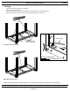
© Panduit Corp. 2016 INSTALLATION INSTRUCTIONS CM599L WARNING CABINET TIPPING HAZARD Ganging of cabinets only provides limited stability to the cabinets, and is not a substitute for proper leveling or floor mounting of cabinets. Ensure that cabinets are properly mounted to floor before equipment is installed in cabinet. (See page 7) FAILURE TO FOLLOW THESE INSTRUCTIONS CAN LEAD TO SERIOUS INJURY, DEATH, OR DAMAGE TO YOUR EQUIPMENT.
© Panduit Corp. 2016 INSTALLATION INSTRUCTIONS CM599L WARNING CABINET TIPPING HAZARD Ganging of cabinets only provides limited stability to the cabinets, and is not a substitute for proper leveling or floor mounting of cabinets. Ensure that cabinets are properly mounted to floor before equipment is installed in cabinet. (See page 7) FAILURE TO FOLLOW THESE INSTRUCTIONS CAN LEAD TO SERIOUS INJURY, DEATH, OR DAMAGE TO YOUR EQUIPMENT.
© Panduit Corp. 2016 INSTALLATION INSTRUCTIONS CM599L DANGER ELECTRICAL SHOCK HAZARD Each cabinet must be connected to the Common Bonding Network (CBN). FAILURE TO FOLLOW THESE INSTRUCTIONS CAN LEAD TO SERIOUS INJURY, DEATH, OR DAMAGE TO YOUR EQUIPMENT.
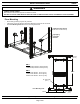
© Panduit Corp. 2016 INSTALLATION INSTRUCTIONS CM599L WARNING FALLING EQUIPMENT HAZARD Remove all equipment installed onto equipment rails before performing any adjustments to equipment rail spacing. FAILURE TO FOLLOW THESE INSTRUCTIONS CAN LEAD TO SERIOUS INJURY, DEATH, OR DAMAGE TO YOUR EQUIPMENT. Equipment Rail Adjustment • Loosen M10 Hex Head Screw at top and bottom of rear equipment rail • Adjust equipment rail to desired positon • Tighten M10 Hex Head Screw to 30.0 +/- 5.0 N-m [22.1 +/- 3.
© Panduit Corp. 2016 INSTALLATION INSTRUCTIONS CM599L Equipment Rails (Zero RU QuickNet™ Patching Adapter Installation) • • • Insert plastic Patching Adapters by snapping adapter into rear-facing surface of rear equipment rails. Patching Adapters accommodate Panduit QuickNet™ Copper and Fiber Cabling Systems (optional) Included on select 600mm wide S-Type cabinet configurations Insert Patching Adapters (snap into equipment rails) For Technical Support: www.panduit.com/resources/install_maintain.
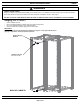
© Panduit Corp. 2016 INSTALLATION INSTRUCTIONS CM599L Overhead Cable Openings • • • • • Remove Bezel Insert to allow for overhead cable entry Cut [8] tabs with wire cutter to open large cable openings - OPTIONAL Install M10 threaded rod into [6] tapped holes for 1070mm deep cabinets or [9] tapped holes for 1200mm deep cabinets, if desired [2] 165.1mm x 165.1mm [6.5” x 6.
© Panduit Corp. 2016 INSTALLATION INSTRUCTIONS CM599L Cable Management Fingers (SN15F, SN25F) • • Insert tabs of Cable Management Finger into mounting slots of cabinet post Slide Cable Management Finger inward to lock into place Cable Managment Finger -Insert tabs into cabinet post -Slide inward to lock in place For Technical Support: www.panduit.com/resources/install_maintain.
© Panduit Corp.
© Panduit Corp. 2016 INSTALLATION INSTRUCTIONS CM599L Single Hinge Door (Removal and Installation) • • • VIEW 1 Pull down Compression Sleeve at top door hinge VIEW 1 Pull Single Hinge Door away from cabinet so that Top Hinge Screw fits through cutout of door VIEW 2 Lift bottom of door off Bottom Hinge Pin Top Hinge Screw Compression Sleeve (Pull down) VIEW 1 VIEW 3 VIEW 2 Bottom Hinge Pin Plastic Washer For Technical Support: www.panduit.com/resources/install_maintain.
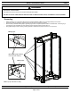
© Panduit Corp. 2016 INSTALLATION INSTRUCTIONS CM599L Single Hinge Door (Door Handle Direction Reversal) • • • • VIEW 1, 2 Remove Top and Bottom Hinge Brackets from current location (remove top hinge screw, if necessary) VIEW 1, 2 Install Top and Bottom Hinge Brackets on opposite side of cabinet (re-install top hinge screw, if necessary) VIEW 3 Move Door catch to opposite side of cabinet frame VIEW 4, 5 Remove Horizontal Grounding Bracket and reinstall on opposite side of door.
© Panduit Corp. 2016 INSTALLATION INSTRUCTIONS Rear Split Doors (Removal and Installation) • • • Open Rear Split Doors to approximately 90º Lift Rear Split Doors up pull doors away from cabinet frame REVERSE STEPS to install Rear Split Doors For Technical Support: www.panduit.com/resources/install_maintain.
© Panduit Corp.
© Panduit Corp.
© Panduit Corp. 2016 INSTALLATION INSTRUCTIONS PDU Bracket Adjustment • • • • PDU brackets are height-adjustable if PDU spacing other than the factory position is desired. Remove [2] M5 Torx Screws per bracket, as shown below Reposition brackets at desired distance, ensuring that mounting flange of PDU bracket rests on the outside of cabinet post.
© Panduit Corp. 2016 INSTALLATION INSTRUCTIONS CM599L Cable Management/PDU Bracket Adjustment (optional) • • • • Cable Management/PDU brackets are height-adjustable if PDU spacing other than the factory position is desired. Remove [4 -or- 6] M5 Torx Screws from bracket, as shown below Reposition bracket at desired height, ensuring that mounting flange of bracket rests on the outside of cabinet post.
© Panduit Corp. 2016 INSTALLATION INSTRUCTIONS Cabinet Sealing Install [6] Latch Plugs [3 upper, and 3 lower] into the door latch cut-outs to the front side of the cabinet only. Install [2] foam seals to the upper and lower frame. Seal should be pressed up against the Equipment Rails, behind the latch plugs. [3] Latch Plugs Foam Seal Foam Seal [3] Latch Plugs For Technical Support: www.panduit.com/resources/install_maintain.
© Panduit Corp. 2016 INSTALLATION INSTRUCTIONS CM599L Front and Rear Floor Seal Installation (Vertical Exhaust Duct ONLY) • Install Floor Seal to front or rear of cabinet frame using (2) M10x20mm Bolts. (Flange on floor seal will face outward away from the cabinet.) [2] M10x20mm Bolts (use 15mm socket wrench) Floor Seal For Technical Support: www.panduit.com/resources/install_maintain.
© Panduit Corp. 2016 INSTALLATION INSTRUCTIONS CM599L Top of Cabinet Cable Manager Installation • • • Disassemble front fascia assemblies (packaged in cabinet) by removing (2) M5x0.8 button head screws (use T25 Torx bit). Remove (2) M5x0.8 button head screws (use T25 Torx bit) from front and rear of Cable Manager base. Install vertical walls on front and back of Cable Manager base using (5) M5x0.8 button head Torx screws (use T25 Torx bit). Re-install screws from previous step to secure to the frame.
© Panduit Corp. 2016 INSTALLATION INSTRUCTIONS CM599L Top of Cabinet Cable Manager Installation (for vertical exhaust ducts) IMPORTANT - INSTALL VERTICAL EXHAUST DUCT PRIOR TO INSTALLING REAR VERTICAL WALL • Disassemble front fascia assemblies (packaged in cabinet) by removing (2) M5x0.8 button head screws (use T25 Torx bit). • Remove (2) M5x0.8 button head screws (use T25 Torx bit) from front of Cable Manager base. • Install vertical wall on front of Cable Manager base using (5) M5x0.
© Panduit Corp. 2016 INSTALLATION INSTRUCTIONS CM599L THIS PAGE IS INTENTIONALLY BLANK For Instructions in Local Languages and Technical Support: www.panduit.com/resources/install_maintain.asp www.panduit.com Page 27 of 27 E-mail: techsupport@panduit.