TDP42H, TDP43H, TDP46H Thermal Transfer Printer OPERATOR MANUAL GMTDPH-MAN
PANDUIT ® Corp. Identification Products Division 1819 Atlanta Hwy. Cumming, GA 30040-1069 Phone: 800-777-3300 Fax: 708-532-1811 email: id-support@panduit.com website: www.panduit.com Copyright ©PANDUIT Corp. 2004 All Rights Reserved.
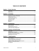
TA B L E O F C O N T E N T S Section 1. Printer Overview Introduction ......................................................................................................1-1 Specifications....................................................................................................1-2 Section 2. Installation Introduction ......................................................................................................2-1 Unpacking and Parts Identification ......................................
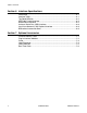
Table of Contents Section 6. Interface Specifications Introduction ......................................................................................................6-1 Interface Types..................................................................................................6-1 The Receive Buffer ..........................................................................................6-2 IEEE1284 Parallel Interface..............................................................................
SECTION 1. Printer Overview Introduction The PANDUIT ® TDP42H, TDP43H and TDP46H Thermal Transfer Printers, hereafter referred to as TDP4*H, are complete, high-performance on-site labeling systems. All printer parameters are user programmable using the front panel controls and the DIP switches. All popular bar codes and 14 human-readable fonts, including a vector font and two raster fonts, are resident in memory providing literally thousands of type styles and sizes.
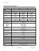
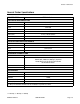
Section 1: Overview General Printer Specifications SPECIFICATION PRINT TDP42H TDP43H Method Speed (User Selectable) Print Module (Dot Size) Resolution TDP46H Direct or Thermal Transfer 2 to 10 ips 50 to 250 mm/s .0049 in. .125mm 203 dpi 8 d/mm Maximum Print Width Maximum Print Length 49.2 in. 1249 mm 2 to 8 ips 50 to 200 mm/s .0033 in. .083 mm 305 dpi 12 d/mm 4.1 in. 104mm 32.8 in. 835 mm 2 to 6 ips 50 to 150 mm/s .0017 in. .081 mm 609 dpi 24 d/mm 14.0 in. 356 mm MEDIA 32.8 in.
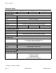
Section 1: Overview General Printer Specifications SPECIFICATION CONTROLS AND INDICATORS TDP4*H Series Power Green LED On-Line Green LED Label Red LED Ribbon Red LED Error Red LED LCD Panel 2 Line x 16 Character Label Feed Front Panel Power On/Off Switch Front Panel PONTENTIOMETER ADJUSTMENTS Print Darkness Front Panel Offset Front Panel Pitch Front Panel Display Front Panel INTERFACE CONNECTIONS Parallel Serial Universal Serial Bus Ethernet (1) IEEE1284 Standard RS232C (9600 t
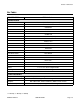
Section 1: Overview Character Fonts SPECIFICATION MATRIX FONTS TDP42H TDP43H TDP46H U Font 5 dots W x 9 dots H S Font 8 dots W x 15 dots H M Font 13 dots W x 20 dots H XU Font 5 dots W x 9 dots H (Helvetica) XS Font 17 dots H x 17 dots W (Univers Condensed Bold) XM Font 24 dots H x 24 dots W (Univers Condensed Bold) OA Font (OCR-A) 15 dots W x 22 dots H 22 dots W x 33 dots H 44 dots W x 66 dots H OB Font (OCR-B) 30 dots W x 36 dots H 30 dots W x 36 dots H 60 dots W x 72 dots H AUTO
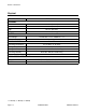
Section 1: Overview Bar Codes SPECIFICATION SYMBOLOGIES TDP4*H Series Linear Bar Codes Bookland (UPC/EAN Supplemental) EAN-8/EAN-13 CODABAR CODE 39 CODE93 CODE 128 Interleaved 2 of 5 (1 2/5) Industrial 2 of 5 Matrix 2 of 5 MSI POSTNET UCC/EAN UPC-A/UPC-E Data Matrix Two Dimensional Maxicode PDF417 Micro PDF Truncated PDF QR Code Ratios 1:2, 1:3, 2:5, User Programmable Bar Height 4 to 999 dots, User Programmable Rotation 0°, 90°, 180° and 270° Rotation OTHER FEATURES Sequential Numbering Custom C
Section 1: Overview Physical SPECIFICATION PHYSICAL TDP4*H Series Wide 10.4 in. (265 mm) Deep 17.1 in. (435 mm) High 13.4 in. (341 mm) Weight 39.7 lb. (18.
Section 1: Overview Optional Accessories ACCESSORIES AND OPTIONS PCMCIA MEMORY EXPANSION One slot for PCMCIA Memory Card ( up to 4 MB SRAM or 16 MB Flash ROM). Can be used for graphic file storage, print buffer expansion, format storage and downloaded fonts. FLASH ROM EXPANSION Internal 4 MB Flash ROM PCB. REAL TIME CLOCK An internal Date/Time clock that can be used to date/time stamp labels at the time of printing.
Section 1: Overview Notes Page 1-8 GMTDPH-MAN PANDUIT TDP4*H
SECTION 2. Installation Introduction This section of the manual has been written to help you install the PANDUIT ® TDP4*H Series printers and to get started as quickly as possible. It is recommended to read each chapter in this manual before the installation of the use of the printers.
Section 2: Installation Unpacking and Parts Identification Consider the following when unpacking the printer: • • • • • The box should stay right-side up. Lift the printer out of the box carefully. Remove the plastic covering from the printer. Remove the accessory items from their protective containers. If the printer has been stored in a cold environment, allow it to reach room temperature before powering it on. • Set the printer on a solid, flat surface.
Section 2: Installation Verify that you have the following materials when unpacking: • • • • Printer Power Cord and Extra Ribbon Core Operator’s Manual CD-ROM Printer CD-Rom Power Cord Ribbon Core Operator Manual Setting Up the Printer Consider the following when setting up the printer: • Locate a solid flat surface with adequate room to set the printer. Make sure there is enough room at the top and right-hand (facing the printer) side to provide clearance for the label access door to swing open.
Section 2: Installation Ribbon Rewind Spindle Ribbon Supply Spindle Top Access Door Side Access Door LCD Display Dip Switch Cover Power Switch Label Hold Down Label Roll Retainer Label Supply Spindle Label Guide Print Head Head Latch Platen Page 2-4 GMTDPH-MAN PANDUIT TDP4*H
Section 2: Installation Loading Labels and Tags 1. Open the Top Access Door by swinging it up and to the left. Open the Side Access Door by swinging it to the rear of the printer Top Access Door Side Access Door 2. Open the Print Head Assembly by pushing the Head Latch toward the rear of the printer. The Print Head assembly is spring-loaded and will automatically open as soon as the Head Latch is disengaged. 3.
Section 2: Installation 5. If using roll labels (or tags), load the roll onto the Label Supply Spindle so that the printing side of the labels faces upwards as it unwinds from the roll. The labels should be wound face-in. Push the roll all the way to the inside of the printer and push the Label Roll Retainer snugly against the outside of the label roll. 6. If using fanfold labels (or tags) set them on a flat surface behind the printer.
Section 2: Installation Inside Label Edge Guides Label Hold Down Route Labels Under Guide Sensor Assembly Sensor Positioning 11. Adjust the outside Label Edge Guide until it touches the outside edge of the label and tighten the thumb screw. Make sure the labels are also touching the inside edge guides. CAUTION: Using media narrower than the maximum print width may cause excess head wear due to the label edge. See page 2-9 for precautions. 12.
Section 2: Installation Loading the Ribbon Ribbon Path Ribbon Roll Ribbon Rewind Spindle Head Latch Dispensed Label Label Backing Sensor Assembly Label Hold Down 1. Open the Top Access Door by swinging it up and to the left and the Side Access Door by swinging it toward the rear of the printer. Label Patch Top Access Door Side Access Door 2. Open the Print Head by rotating the Head Latch toward the rear of the printer.
Section 2: Installation Tape 8. If the labels or tags are already loaded, close the Print Head Assembly by pushing downward on the green tab until it latches closed. Ribbon Core 9. Run a test print to ensure that the labels and ribbons were loaded correctly. CAUTION: If your labels are less than the full width of the print head, the outside edge will eventually wear out a small portion of the print head, resulting in an area that will not print.
Section 2: Installation Operator Panel LCD DISPLAY PANEL LINE FEED POWER LABEL PRINT RIBBON OFFSET ERROR PITCH ON LINE DISPLAY Not Used DSW2 DSW3 The PANDUIT ® TDP4*H Operator Panel consists of five LED indicators, two momentary contact switches, three DIP switches, four adjustment potentiometers and one LCD Display. All of these are accessible from the front of the printer. They are used to set the printer operating parameters and to indicate the status of the printer to the operator.
Section 2: Installation ON LINE LED, illuminated when printer is ready to receive data. Toggled on/off with LINE key. LINE Momentary switch. Pressing this key toggles the printer between the on-line and off-line mode. When the printer is on-line, it is ready to receive data from the host. This key acts as a pause during a print job by taking the printer off-line. It can also be used as a Pause function key to stop the printer during the printing process. FEED Momentary switch.
Section 2: Installation Rear Panel AC INPUT Input 115 VAC, 50/60 Hz connector. Use cable provided. AC FUSE Input power protection. 3A/250V rating. INTERFACE SLOT Connector for Plug-In Interface Module. MEMORY CARD SLOT Connector for optional PCMCIA Memory Card. EXT External signal connector, AMP 57-60140.
Section 2: Installation Sensors The TDP4*H printers contain three sensing units; a Ribbon End motion sensor, a Head Open microswitch and a Label Indexing Sensor RIBBON END SENSOR Detect motion of the Ribbon supply spindle and signals the printer when it is turning. HEAD OPEN SENSOR A micro-switch that is activated when the head is unlatched. LABEL INDEXING SENSOR The sensing assembly contains two types of sensors, one for label gap and one for eye-mark sensing.
Section 2: Installation Notes Page 2-14 GMTDPH-MAN PANDUIT TDP4*H
SECTION 3. Configuration Printer Dip Switch Configuration DIP SWITCH PANELS There are two DIP switches (DSW2 and DSW3) located on the front panel under a protective cover. In addition, a third DIP switch is located on the RS232C Serial Adapter card and is used to set the RS232C transmit/receive parameters.
Section 3: Configuration Stop Bit Selection (DSW1-4). Selects the number of stop bits to end each byte transmission. DSW1 DSW1-4 SETTING Off 1 Stop Bit On 2 Stop Bits ON OFF 1 2 3 4 5 6 7 8 6 7 8 Baud Rate Selection (DSW1-5, DSW1-6). Selects the data rate (bps) for the RS232 port. DSW1-5 DSW1-6 SETTING DSW1 Off Off 9600 ON Off On 19200 On Off 38400 On On 57600 OFF 1 2 3 4 5 Protocol Selection (DSW1-7, DSW1-8). Selects the flow control and status reporting protocols.
Section 3: Configuration Sensor Type Selection (DSW2-2). Selects between the use of a label gap or a reflective Eye-Mark detector. DSW2 DSW2-2 SETTING Off Gap On Eye-Mark ON OFF 1 2 3 4 5 6 7 8 Head Check Selection (DSW2-3). When selected, the printer will check for head elements that are electrically malfunctioning. DSW2 DSW2-3 SETTING Off Disabled On Enabled ON OFF 1 2 3 4 5 6 7 8 2 3 4 5 6 7 8 Hex Dump Selection (DSW2-4). Selects Hex Dump mode (see page 3-21).
Section 3: Configuration Firmware Download (DSW2-6). Places the printer in the Firmware Download mode for downloading new firmware into flash ROM. DSW2 DSW2-6 SETTING Off Disabled On Enabled ON OFF 1 2 3 4 5 6 7 8 Protocol Code Selection (DSW2-7). Selects the command codes used for protocol control. Refer to page E-1 for more information. DSW2 DSW2-7 SETTING Off Standard On Non-Std ON OFF 1 2 3 4 5 6 7 8 Status Select (DSW2-8). For emulating earlier series software commands.
Section 3: Configuration Label Sensor Selection (DSW3-3). Enables or disables the Label Sensor. If the Sensor is enabled, it will detect the edge of the label and position it automatically. If it is disabled, the positioning must be under software control using Line Feed commands. DSW3 DSW3-3 SETTING Off Not Used On Sensor Used ON OFF 1 2 3 4 5 6 7 8 Back-Feed Selection (DSW3-4).
Section 3: Configuration External Signal Type Selection (DSW3-6, DSW3-7). Both the polarity and signal type (level or pulse) of the external print synchronizing signal can be selected. DSW3-6 DSW3-7 SETTING DSW1 Off Off Type 4 ON Off On Type 3 On Off Type 2 On On Type 1 OFF 1 2 3 4 5 6 7 8 Repeat Print via External Signal (DSW3-8). Allows the applicator to reprint the current label in the print buffer.
Section 3: Configuration Default Settings SWITCH SELECTIONS All switches are placed in the Off default position for shipping.
Section 3: Configuration Potentiometer Adjustments PITCH After the pitch has been set with the LCD Control Panel, it is sometimes desirable to make minor adjustments. This can be done using the PITCH potentiometer on the top panel. This potentiometer is set at the factory so that it has a range of +/- 3.75 mm. The midpoint setting should have no effect on the pitch. Turning the potentiometer all the way clockwise should move the print position 3.75 mm up towards the top edge of the label.
Section 3: Configuration DISPLAY This potentiometer is used to adjust the contrast of the LCD display for optimum viewing under various lighting conditions. PRINT The PRINT potentiometer is used to adjust the amount of heat (i.e., power) applied to the head for printing. It provides a continuous range of adjustment. Maximum print darkness is obtained by turning the potentiometer all the way clockwise and a maximum counterclockwise setting will give the lightest print.
Section 3: Configuration LCD Panel Printer Configuration The LCD Panel is used by the operator in conjunction with the LINE and FEED switches to manually enter printer configuration settings. Many of these settings can also be controlled via software commands and in the case of conflict between software and control panel settings, the printer will always use the last valid setting.
Section 3: Configuration OFFLINE Press the LINE key once. When the display changes to OFFLINE, press the FEED and LINE keys simultaneously for more than one second. Release the keys. 000000 PRINT DARKNESS 1 2 3 4 5 The LCD now displays the Print Darkness selections. The current setting is indicated by a cursor over one of the range settings. There are 5 possible selections. The lowest setting represents the lightest print and the highest setting the darkest print. 1.
Section 3: Configuration PITCH OFFSET +00mm The label Pitch is the distance from the leading edge (the edge that comes out of the printer first) of a label and the leading edge of the next label. The leading edge position of the label can be adjusted relative to the print head +/- 49mm in increments of 1mm. Once the position is set, it can be fine adjusted +/- 3.75mm using the PITCH potentiometer on the Adjustment Panel. 1. The cursor will initially be positioned over the Pitch Direction setting.
Section 3: Configuration CANCEL PRINT JOB YES NO If the printer has a print job(s) in memory, selecting YES will cause the job(s) to be cleared. The default selection is NO. Be sure you want to cancel the print job(s) before selecting yes as the job(s) cannot be recovered and will have to be retransmitted to the printer. 1. Use the Cursor keys to step the cursor to either the YES or NO selection. 2. Once the correct setting is selected, pressing the ENTER key will accept the setting.
Section 3: Configuration PRINT OFFSET V:+0000 H:+0000 Vertical Offset is the distance down from the leading edge (the edge of the label that comes out of the printer first) to the first vertical print position. A positive setting moves the label edge out of the printer while making it negative moves it back into the printer. Horizontal Offset is distance that the label image is shifted either to the right or left on the label.
Section 3: Configuration CALENDAR 00/00/00 00:00 1. Year - The first display shown will have the cursor over the two digit year selection. You can scroll through the dates by pressing the LINE/FEED keys. The year number will increase by one each time the LINE key is pressed until it reaches its maximum legal value (i.e., “99” for the year digits). Pressing the FEED key will decrease the year number. 2.
Section 3: Configuration CHARACTER PITCH PROP FIXED This selection allows you to set the default character pitch to either fixed character spacing or proportional character spacing 1. Use the LINE key to step the cursor to the desired setting. 2. Once the correct setting is selected, pressing the FEED key will accept the setting and the display will return to the Advanced Mode display ADVANCED MODE To exit the advanced mode, power the printer off and then back on.
Section 3: Configuration TRUETYPE FONTCOPY COMPLETED 4. Once the copy process is completed, press the FEED key to step the display. CARD COPY/FORMAT XXXXXXX ERROR 5. If an error is encountered in the copy process, one of the following messages will be displayed on the second line: R/W Error Indicates a Read/Write error occurred No Card Error Indicates no card was recognized Mem Full Error Indicates that there is insufficient memory available.
Section 3: Configuration CARD->MEMORY COPY COPYING 3. Press the FEED key to accept the selection. If Yes was selected the copy process will start. CARD->MEMORYCOPY COMPLETED 4. Once the copy process is completed, press the FEED key to step the display. CARD COPY/FORMAT XXXXXXX ERROR 5.
Section 3: Configuration CARD->MEMORY COPY COPYING 3. Press the FEED key to accept the selection. If Yes was selected the copy process will start CARD->MEMORYCOPY COMPLETED 4. Once the copy process is completed, press the FEED key to step the display. CARD COPY/FORMAT XXXXXXX ERROR 5.
Section 3: Configuration CARD MODE To exit the Card Mode, power the printer off and then back on. SERVICE MODE The Service Mode allows the operator to set up the basic operation parameters of the printer. V 05.00.03.00 INITIALIZING Displays the firmware during the initialization. ADVANCED MODE The Service Mode is entered from the Advanced Mode display by pressing the LINE key twice. SERVICE MODE The Service Mode display indicates that the printer is in the Card Mode.
Section 3: Configuration GAP INPUT [X.XXV] [X.XV} GAP - When setting the “gap” threshold, the voltage shown on the top line of the display must be measured with nothing but the backing in the sensor and then again with a label still attached to the backing. The formula to be used for setting the threshold is: (High Voltage Level + Low Voltage Level) x 0.5 = Start Value 1. Insert a label still attached to the backing into the sensor and close the Label Hold-Down.
Section 3: Configuration EYE INPUT [X.XXV] [X.XV} EYE - When setting the “eye” threshold, the voltage must be measured with nothing but the label under the sensor and then again with the printed “eye” mark under the sensor. The formula for this is: (High Voltage Level + Low Voltage Level) x 0.5 = Start Value 1. Insert a label into the sensor and close the Label Hold-Down. Make sure the printed “eye” mark is not under the sensor. Record the voltage shown on the top line of the LCD panel.
Section 3: Configuration REPRINT W/FEED YES NO This selection specifies whether or not the printer will print the last printed label stored in memory when the FEED key is pressed in the Normal Online mode. 1. Use the LINE key to step the cursor to desired setting. If Yes is selected, the printer will reprint the last label when the FEED key is pressed when the printer is Online. If the printer is Offline, pressing the FEED key will feed a blank label. 2.
Section 3: Configuration SELECT LANGUAGE ENGLISH This selection allows the user to select the character set used by the printer. The selections are English, French, German, Spanish, Italian and Portuguese. 1. Press the LINE key to advance to the desired language setting. 2. When the setting is correct, press the FEED key to accept the setting and step to the next display.
Section 3: Configuration COUNTERS MODE The Counter Mode is provided to allow the user to access the internal printer counters. ADVANCED MODE The Counter Mode is accessed from the Advanced Mode. Press the LINE key to step to the Counter Mode. COUNTERS MODE Pressing the Feed key will advance the display to the counter selections.
Section 3: Configuration TEST PRINT MODE CONFIGURATION This option allows you to print a test label. It is recommended that you print a test label after you have changed any of the settings in the Advanced Mode. The test label allows you to verify that you indeed did make the desired changes. To enter the Test Print Mode, power the printer on while pressing the FEED key. The printer will beep. Release the FEED key and the printer will display the following message on the LCD panel: 1.
Section 3: Configuration DEFAULT SETTING COMPLETED 3. When the printer has completed the reset process it will beep 3 times and the Default Setting Completed display will appear. At this time the printer is in the default configuration. 4. To exit the Default Setting Mode, power the printer off and then back on. CLEAR NON-STANDARD PROTOCOL The standard protocol codes used by the printer can be modified to accommodate the requirements of different host systems.
Section 3: Configuration USER DOWNLOAD WAITING 2. Press the LINE key. The printer is now waiting for the data to be sent. 3. Transmit the download data command stream to the printer. 4. After the data has been received, the printer will beep and print a status label. If it does not beep and print a status label, the printer did not accept the data. 5. If the printer did not beep and print a status label, turn the printer off and check your data stream for errors and start the download process over. 6.
SECTION 4. Cleaning and Maintenance Introduction The following information is presented in this section: • • • • Adjusting the Print Quality Cleaning the Print Head, Platen and Rollers Replacing the Print Head Replacing the Fuse Adjusting the Print Quality One of the nice features of the PANDUIT ® printers are their high print quality. They are equipped with two different methods of adjusting the quality of the print; print darkness and speed.
Section 4: Cleaning and Maintenance PRINT SPEED The other method of controlling print quality is by controlling the speed at which the label is printed. This adjustment is made only on an individual label basis using the Print speed command code. Changing the print speed allows the user to control the amount of time allowed for print element cooling before the media is stepped to the next print position.
Section 4: Cleaning and Maintenance CLEANING THE PLATEN AND ROLLERS 1. Turn the printer off and remove the power cable. 2. Open the Top and Side Access doors. 3. Open the Print Head Assembly by rotating the Head Latch toward the rear of the printer. The Print Head Assembly is spring-loaded and will automatically open as soon as the Head Latch is disengaged. 4. Unlatch the Label Hold-Down by lifting up on the latch lever (immediately below the green PUSH tab. ® 5.
Section 4: Cleaning and Maintenance 3. Open the Print Head by pushing the Head Latch toward the rear of the printer. The Print Head is spring loaded and will automatically open as the Head Latch is disengaged. 4. Remove the ribbon. 5. Apply PANDUIT ® Thermal Print Head Cleaner to a cotton swab. 6. Carefully insert the swab between the top and bottom portions of the Sensor Assembly. The location of the sensors is identified by two marks on the assembly. 7.
Section 4: Cleaning and Maintenance 7. Disconnect the signal and power cables from the print head connectors and set the Print Head aside. There are two connectors on the signal cable. The smaller connector is used for the 203 and 305 dpi print heads, the larger one for the 609 dpi print head. Note which connector was connected to the print head. DO NOT remove the two outside screws (painted red) on either side of the center mounting screw.
Section 4: Cleaning and Maintenance Notes Page 4-6 GMTDPH-MAN PANDUIT TDP4*H
SECTION 5. Troubleshooting Introduction This section has been devised to help you if you are unable to produce output on the TDP4*H printers. Use this section to make sure the basics have been checked before deciding you are unable to proceed any further. The section is divided into five parts: • • • • • Initial Checklist IEEE1284 Parallel Interface RS232C Serial Interface Universal Serial Bus Interface LAN Ethernet Interface Initial Checklist 1. Is the printer powered up and ON-LINE? 2.
Section 5: Troubleshooting 6. When you send the print job to the printer and it does not respond, and there is no error message on the PC: a. Check your data stream for some of the basics. Is your job framed as follows? A—DATA—Z b. Verify that you’ve included all required parameters in the data stream. c. Verify the following: You have not typed a “0” (zero) for an “O” (letter) or vice-versa. You have not missed any characters where they’re needed.
Section 5: Troubleshooting 4. Check for obvious errors in the data stream. Is the data properly framed with the A and Z commands? 5. If after sending your job to the printer, it only “beeps” and displays an error message on the LCD display, you may have a configuration problem. There may be some inconsistencies with the Baud Rate, Parity, Data Bits, or Stop Bits in relation to your host computer.
Section 5: Troubleshooting •There is a queue setup problem, a print server setup problem, or other protocol-related problem. CHECKING THE INTERFACE BETWEEN THE PRINT SERVER AND THE PRINTER First make sure that the cable between the print server and printer is securely plugged in at both sides. Then: 1. Wait about two minutes after the printer is powered on and then run a printer self-test (see Section 3: Configuration for information on how to run the self-test).
Section 5: Troubleshooting Using the Lan Ethernet Interface The LCD Display, Front Panel LED indicators and Buzzer provide a visual/audio indication of the type of error encountered. LCD MESSAGE AUDIBLE BEEP ERROR CONDITION Error On LED Machine Error 1 Long Machine Error Error On EEPROM Error 1 Long EEPROM Read/Write Error On Head Error 1 Long Head Error On Sensor Error 3 Short Sensor Error Blinks Card R/W Error 1 Long Memory Card Read/Write 1. Card not formatted. 2.
Section 5: Troubleshooting Notes Page 5-6 GMTDPH-MAN PANDUIT TDP4*H
SECTION 6. Interface Specifications Introduction The TDP4*H printers utilize a Plug-In Interface Module for maximum printer configuration flexibility. This section presents the interface specifications for the TDP4*H printers. These specifications include detailed information on how to properly interface your printer with your host system.
Section 6: Interface Specifications WARNING: Never connect or disconnect interface cables (or use a switch box) with power applied to either the host or the printer. This may cause damage to the interface circuitry in the printer/host and is not covered by warranty. The Receive Buffer The TDP4*H printers have the ability to receive a data stream from the host in one of two ways. The receive buffer may be configured to accept one print job at a time or multiple print jobs.
Section 6: Interface Specifications 2.0 MB 2.95 MB Buffer Near Full DTR Low or X-Off 0 DTR High or X-On The receiving buffer will not be able to receive more data again until a “Buffer Available” condition occurs. This takes place when the receiving buffer has emptied so that only 1 MB bytes of data are being held (2.0 MB bytes from being full). At this time, DTR will go “high” or an X-On is sent to tell the host that it can again receive data. 0 1.0 MB DTR Low or X-Off 2.
Section 6: Interface Specifications ELECTRICAL SPECIFICATIONS Printer Connector AMP 57-40360 (DDK) or equivalent Cable Connector AMP 57-30360 (DDK) or equivalent Cable IEEE1284 Parallel, 10 ft. (3 m) or less Signal Level High = +2.4V to +5.0V Low = 0V to -0.4V DATA STREAMS A . . Job#1 . . ZA . . Job#n . .
Section 6: Interface Specifications 18 1 36 19 RS232 Serial Interface The High Speed Serial Interface is a Plug-In Interface Module that can be installed in the printer by the user.
Section 6: Interface Specifications PIN ASSIGNMENTS RS232C Interface Signals Page 6-6 PIN REFERENCE SIGNAL DEFINITION 1 Reference 2 To Host TD (Transmit Data) - Data from the printer to the host computer. Sends X-On/X-Off characters or status data (Bi-directional protocols). 3 To Printer RD (Receive Data) - Data to the printer from the host computer. 4 To Host RTS (Request to Send) - Used with Ready/Busy flow control to indicate an error condition.
Section 6: Interface Specifications CABLE REQUIREMENTS DB9 DB25 HOST INTERCONNECTION DB25 PRINTER 1 1 FG 1 FG (Frame Ground) 2 3 RD 2 TD (Transmit Date) 3 2 TD 3 RD (Receive Data) 8 5 CTS 4 RTS (Request to Send) 7 4 RTS 5 CTS (Clear to Send) 4 20 DTR 6 DSR (Data Set Ready) 6 6 DSR* 20 DTR (Data Terminal Ready) 5 7 SG 7 SG *(Signal Ground) * This connection at the host side of the interface would depend upon the pin that is being used as the Ready/Busy signal
Section 6: Interface Specifications Universal Serial Bus (USB) Interface The Universal Serial Bus (USB) interface is a Plug-In Interface Module that can be installed by the user. It requires a driver (shipped with each printer that has the interface installed) that must be loaded on your PC and the PC must be configured to support USB peripherals using Windows 98 or above.
Section 6: Interface Specifications ENQUIRE/ACK/NAK In the Bi-Com 4 mode, the host transmits an ENQ (05 hexadecimal) to the printer and the printer will respond with its status within five milliseconds. If printing, it will respond upon finishing the current label, then resume printing. In order for this protocol to work properly with an RS232C Optional Interface, pin 6 (DTR) and pin 5 (CTS) must be held high by the host.
Section 6: Interface Specifications PRINT STOP (DLE) If a DLE (10 hexadecimal) is received by the printer, the print process is stopped and an ACK (06 hexadecimal) is returned if there are no errors and a NAK (16 hexadecimal) if a printer error exists. PRINT START (DC1) If the printer has been stopped by receipt of a DLE (10 hexadecimal) command, it can be restarted by sending a DC1 (hexadecimal 11) command.
SECTION 7. Optional Accessories Introduction This section contains instructions for using the following features: • • • • • • PCMCIA Memory Cards Plug-In Interface Modules Cutter Dispenser Label Rewinder Real Time Clock PCMCIA Memory Cards DESCRIPTION The Memory Card Option provides the connectors and interface board for one PCMCIA memory cards slots. The printer memory can be expanded up to 16MB. Type SRAM or Flash-ROM Applicable Specifications PCMCIA Version 2.1 (JEIDA Version 4.
Section 7: Optional Accessories ERROR DESCRIPTION INDICATION REMEDY Low Battery - Low battery condition is detected when printer is powered on. ERROR LED: Blinking Audible Beep: 1 Long Display: Card Low Battery Card R/W Error 1. No Card is inserted. 2. Card is write protected. 3. Invalid store/recall number. 4. Card has not been initialized. Warning 1. Duplicate number. 2. Data not in print area. 3. Data overflows card memory. ERROR LED: On 1. Insert card into selected slot.
Section 7: Optional Accessories Cutter The label cutter consists of an internal mechanism that will cut labels or tags as they exit from the printer. The cutter can be used to print labels of various lengths using continuous form label/tag stock or to easily separate labels when there is no perforation at the label gap. OPERATOR SETUP The following steps should be taken to set up the label cutter. 1. Install the label cutter, following the instructions provided with the unit. 2. Power the printer ON. 3.
Section 7: Optional Accessories Label Dispense Option The TDP4*H Label Dispense Option is an external mechanism that provides the ability to print labels in the “demand” mode. It is attached to front of the printer. When the label dispenser is installed and configured for operation, the printer dispenses one label at a time, peeling the backing from the label, which allows for immediate application to the product by the operator. OPERATOR SETUP 1.
Section 7: Optional Accessories Label Rewinder The rewinder is an external unit that allows for labels and tags to be rewound in rolls up to 8.5 inches in diameter. It derives its power directly from the printerÌs EXT connector using a built-in cable. The rewinder provides the ability to rewind tags/labels from the printer and subsequently be unwound for later use with applicators. INSTALLATION 1. Position the Rewinder at the front of the printer and align it with the label slot.
Section 7: Optional Accessories Real Time Clock The Real Time Clock Option allows the date and time to be maintained in the local printer rather than using the system clock. It consists of a special clock chip that replaces the EPROM on the main pcb assembly. A qualified technician should perform the upgrade as it requires modifications to the main PCB assembly. Please call PANDUIT ® Technical Support if you need to add this option to an existing printer in the field.