Panowin F1 User Manual
PANOWIN TECHNOLOGIES CO.,LTD.
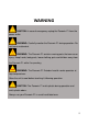
WARNING CAUTION: In case of emergency unplug the Panowin F1 from the power outlet. WARNING: Carefully monitor the Panowin F1 during operation. Do not leave unattended. WARNING: The Panowin F1 contains moving parts that can cause injury. Keep hands, body parts, loose clothing, pets and children away from the Panowin F1 while it’s operating. WARNING: The Panowin F1 Extruder head & nozzle operates at high temperatures. Allow the unit to cool before touching it following operation.
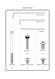
Tools & Screws Large Hex Key Small Hex Key Tweezers 3 M3X18mm M4X10mm 18X 4X M3X50mm M3X6mm(Round Head) M3X8mm(Flat Head) 6X 2X 7X
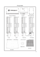
Components Main Control Board Extruder Extruder Mounting No Switch X Axis Y Axis (Green Connector) (Red Connector) Z Axis Left (Yellow Connector) Z Axis Right (Yellow Connector) Rubber Foot Print Bed Base Plate 4
Panowin F1 Mechanical Assembly
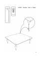
Large Hex Key STEP1.
STEP2.
STEP3.
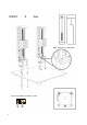
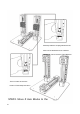
Manually rotate the coupling attached to the bottom of the threaded rods in a leftward direction in order to move the Z Axis Blocks to This is to make sure the two blocks of Z Axis keep level when STEP4.
STEP5.
STEP6.
STEP7.
STEP8.
STEP9.
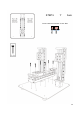
DONE Z Axis Right Extruder 15 Main Control Board Print Bed Z Axis Left Y Axis X Axis
Panowin F1 Cable Connection
1.
2.
3.
4.
Panowin F1 Quick Start
1. Connect the Cable of Power Supply and USB Plug the cable of power supply and USB into the according interfaces on the right side of the main control board, and connect the other end of USB cable to the slot of you PC. 2. Install USB Driver Find the USB Driver in the accessary SD card, and click SETUP.EXE to install the driver.
You can find the according COM port number in the Device Manager, which indicates that the driver has been installed properly.
3. Launch Pango Find Pango in the accessary SD card, and uncompress the zip file into your disk. Double click paogo.exe to launch it, choose “ Panowin F1” in the Machine Option dialog, and press the button to enter the main interface of Pango.
25
4. Open Serial Console Select the menu “View”->“Console”, click the “Console” button in the following dialog ,to open the serial console in pango. The basic functions of the console are as follows: Extruder Control Nozzle Temperature HBP Temperature Axis Control Command Line SD Card Print Control SD Card Printing You can also make your cursor hovering on any button to get the tip for its function.
27
5. Calibrate the Z Axis Offset When the Extruder is at the home position of Z Axis, we need to make sure that the distance between the nozzle and print bed is close to zero, no more, no less, in order to make the print model attached to the print bed well. If the nozzle is too high, the model will not stick well on the print bed. If the nozzle is too low, the filament can’t come out smoothly and it will even damage the print bed.
Therefore, please follow the steps bellow to calibrate the Z Axis Offset when you have assembled the machine for the first time. (1) Click the “Home X” and “Home Y” button to home the XY axes. (2) Drag the slide bar of XY Axes, to move the Extruder to an approaching position of the Print Bed Center. (3) Click the “Home Z” button, and wait until the Z Axis finished the homing operation.
(4) Estimate the offset from the nozzle to the print bed, take the print bed as zero point, if the nozzle is higher than the bed, the offset is a positive value, and if the nozzle is pressing the bed, the offset is a negative value. Positive Offset(+) Zero Offset(0) Negative Offset(-) (5) For example, the nozzle is 0.3mm far away from the print bed after Z Axis homing, so the offset value should set to be 0.3. Click the “Z offset” button on the console, and input the value “0.
(6) The printer will auto home Z Axis, and move down 0.3mm to compensate the offset. If the value is proper, the nozzle will exactly hit the print bed. But if not, you can adjust the value and try more times until you get a good result. 6. Feed the filament (1) Click the “Heat E” button and wait until the nozzle temperature reach preset value (200 C).
(3) Click the “Extrude” button to test the extruding of the filament. 7. Quick Print You can start the print after the Z Offset calibration, filament feeding and extruding test. There is a file named “autoprint.pcode”(filament holder) in the accessary SD card, you can just insert the SD card to the machine to launch the Auto Printing, to make a quick print.
saves the redundant operations while using PC connection or user interfaces, and make the print work more convenient and fast: (1) Save the sliced file name as “autoprint.pcode” and copy the file into SD card. (2) Insert the SD card to the machine, the printer will auto start the print work with twice “beep”, if the file is validated. (3) If you need to stop the print work, just remove the SD card, the printer will auto stop.
Panowin F1 Slicing Guide 34
1. Load Models (1) Click the “Load Model” button on the right tool bar. (2) Select the model of the supported formats (STL, DAE or OBJ) to load.
2. Adjust Model (1) Click the “Move” button,to move the model, with default interval of 10mm, if dragging the model with the SHIFT key pressed, you can move it with any offset. (2) Click the “Scale” button,to resize the model.
37
(3) Click the “Rotate” button, select the corresponding axis, roll the middle wheel of your mouse, to rotate the model in a certain direction, with a default increasing degree of 15. If rolling with the SHIFT key pressed, you can rotate the model with any degrees. 3. Slice Preview (1) Click the “View Layer” button to slice the model and preview. The slice information, such as the weight of filament, time cost, will be showed on the right top of the interface.
(2) You can also drag the slider bar on the left side , to check the slice results of any layers. 4. Save PCODE Click the “Save CODE” button to save the slice data as a pcode file, and copy the pcode file to the SD card to print it with Panowin F1. If you want to do the “Auto Printing”, please save the file as “ autoprint.pcode”. If you use Pango Console or LCD Interface to control the print process, you can save the file with any name.
40
Copyright © 2013, Panowin Technologies, Co,. Ltd. All Rights Reserved. Copyright Notice Panowin copyrights this manual. No part of this manual may be reproduced in any form or means, without the prior written consent of Panowin. Disclaimer This manual is preliminary and is subject to change at any time without notice. Panowin assumes no Tele:021-60950805 021-60950806 Fax: 021-60950807 Email:service@panowin.com Website:www.panowin.