220 GYM SYSTEM WARNING: Read and follow all directions for each step to insure proper assembly of this product. USER’S GUIDE CLASS H PART # 7017301 REV.
TABLE OF CONTENTS Safety Statement.............2 General Notes..................3 Tools Required................3 Gym Layout.....................4 Parts list..........................5 Assembly Instructions.....6-21 General Maintenance.......22 Warranty Statement..........23 Product Services..............24 Insert-Registration Card IMPORTANT SAFETY INFORMATION THERE IS A RISK ASSUMED BY INDIVIDUALS WHO USE THIS TYPE OF EQUIPMENT. TO MINIMIZE RISK FOLLOW THESE RULES! 1.
IMPORTANT NOTES Please note: * Thank you for purchasing the ParaBody 220 Gym System. Please read these instructions thoroughly and keep them for future reference. * This product must be assembled on a flat, level surface to assure its proper function. DO NOT securely tighten any frame connections until the entire frame has been assembled, unless otherwise stated.
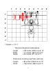
1’ 2’ 3’ 4’ 5’ 6’ 7’ 8’ 1’ 2’ 3’ 4’ 5’ 6’ 7’ 1 Square = 1’ X 1’ Minimum Required Usable Space Length Width Height = 82 inches (208.5 cm) 6’ 10” = 71 inches (180.5 cm) 5’11” = 83 inches (211 cm) 6’ 11” Dimensions Including Leg Press (optional) Length Width = 82 inches (208.5 cm) 6’ 10” = 108 inches (180.
PARTS LIST KEY 1 2 3 4 5 6 7 8 9 10 11 12 13 14 15 16 17 18 19 20 21 22 23 24 25 26 27 28 29 30 DESCRIPTION QTY PART # FRAME 1 7005008 BASE 1 7005708 BASE PLATE 2 6994608 BOOM PLATE LEFT 1 7005308 BOOM PLATE RIGHT 1 7005208 PRESS HANDLE RIGHT 1 7005408 PRESS HANDLE LEFT 1 7005508 PRESS ARM 1 6999708 PRIMARY PIVOT 1 7005108 SEAT ADJUST 1 7005808 LEG PEDESTAL 1 7005608 PULLEY PLATE 2 6940808 SEAT PAD 2 6994721 3/4 X 17” TUBE 3 6549301 4 X 7” ROLLER PAD 6 6194601 72-3/8” GUIDE ROD 2 6523401 ERGO BAR 1 7006202
1 30 3/8 X 3-3/4 2 29 41 3 62 34 34 FIGURE 1 STEP 1: • LOOSELY assemble two BASE PLATES (3) to the FRAME (1) and BASE (2) using four 3/8 X 3-3/4” BOLTS (30) and four 3/8” LOCK NUTS (34). See FIGURE 1.
23 22 FIGURE 2 STEP 2: • Insert two WEIGHT PLATE BUSHINGS (23) into each of the fifteen WEIGHT PLATES (22) as shown in FIGURE 2. 60 19 18 FIGURE 3 STEP 3: • Slide the WEIGHT PLATE SHAFT (18) thru the hole in the HEAD PLATE (19), and lock in place using one E-RING (60) as shown in FIGURE 3.
STEP 4: • Insert two GUIDE RODS (16) into the BASE (2) as shown on FIGURE 4. (NOTE: If the 220 SHROUD OPTION was purchased, place the GUIDE RODS (16) through the BOTTOM SHROUD BRACKET (FOUND IN THE SHROUD KIT BOX) into the BASE (2), as shown in FIGURE 4. 48 16 • (NOTE: Lubricate GUIDE RODS (16) with silicon or teflon spray available at most hardware stores.
FIGURE 6 STEP 6: 6 7 • • • 22 Insert two 1/2” FLANGE BEARINGS (40) into the LEFT PRESS HANDLE (7) as shown in FIGURE 6 22 FLUSH SIDE Using hammer tap one 5/16 X 2” ROLL PIN (47) thru LEFT PRESS HANDLE (7) until it is flush with other side of HANDLE as shown in FIGURE 6 Repeat STEP 6 for the RIGHT PRESS ARM HANDLE (6) 47 40 STEP 7: • NOTE: Place PRESS ARM (8) upside down on floor as shown to complete this step 34 Place LEFT PRESS HANDLE (7) onto PRESS ARM (8).
3/8 X 3” 29 36 Locking 49 Spring Pin 34 FIGURE 8 8 9 STEP 8: • Place PRESS ARM (8) into PRIMARY PIVOT (9) and securely tighten using two 3/8 X 3” BOLTS (29), four 3/8” FLAT WASHERS (36) two 3/8” LOCK NUTS (34) • Insert and tighten two 3/8” LOCKING SPRING PINS (49) into PRESS HANDLES (6), (7). • Lock PRESS ARMS (6), (7) into place using 3/8” LOCKING SPRING PINS (49) • To disengage LOCKING SPRING PINS (49), pull out and twist 1/4 turn.
1 33 1/2 X 8” 37 48 SECURELY TIGHTEN DO NOT 35 TIGHTEN 9 FIGURE 9 STEP 9 • SECURELY TIGHTEN ALL FRAME CONNECTION BEFORE PROCEEDING TO NEXT STEP • SECURELY TIGHTEN top of both SHAFT COLLARS (48) flush to bottom of both BOOM PLATES (4),(5) • Assemble the PRIMARY PIVOT (9) of the PRESS ARM ASSEMBLY to the top of the FRAME (1) using 1/2 X 8” BOLT (33), two 1/2” FLAT WASHERS (37) and 1/2” LOW HT LOCK NUT (35).
13 19 10 36 22 28 3/8 X 2-3/4” 58 61 52 1 50 FIGURE 10 STEP 10: • Apply WEIGHT STACK LABELS (61) to WEIGHTS (22) and HEAD PLATE (19) as shown in FIGURE 10. Begin with number one at the HEAD PLATE (19) with larger numbers in consecutive order towards bottom of weight stack. • Apply four PARAGLIDES (58) to the INSIDE of the tube of FRAME (1) as shown.
55 32 1/2 X 4” 56 40 1 11 35 FIGURE 11 STEP 11: • Insert two 1/2” FLANGE BEARINGS (40) into LEG PEDESTAL (11) as shown.
ILLUSTRATION A • ILLUSTRATION “A” used as cable routing reference for steps 13-16 NOTE: IF YOU PURCHASED A LEG PRESS, PLEASE REFER TO THE CABLE ROUTING INSTRUCTIONS INCLUDED WITH THE LEG PRESS KIT 14
30 3/8 X 3-3/4” 42 1 24 31 3/8 X 8” 36 34 44 9 FIGURE 13 STEP 13: • Refer to cable ILLUSTRATION “A” on page 11 for cable routing while installing pulleys. • Assemble two 3-1/2” PULLEYS (24) into FRAME (1) using two 3/8 X 3-3/4” BOLTS (30), four 3/8 X 1-1/16” FLANGE SPACERS (42) and two 3/8” LOCK NUTS (34) and tighten securely.
24 3/8 X 3-3/4” 30 1 43 42 34 31 3/8 X 8” 36 44 9 27 12 FIGURE 14 STEP 14: • Refer to cable ILLUSTRATION “A” on page 11 for cable routing while installing pulleys. • Assemble one 3-1/2” PULLEY (24) into the PRIMARY PIVOT (9) lower hole using one 3/8 X 8” BOLT (31), two 3/8” FLAT WASHERS (36), two 3/8 X 1-3/16” SPACERS (44) and one 3/8” LOCK NUT (34) and tighten securely.
20 SECURELY TIGHTEN JAM NUT DO NOT 35 OVERTIGHTEN 18 FIGURE 15 51 STEP 15 • Slip ring of WEIGHT SELECTOR PIN (51) down WEIGHT STACK SHAFT (18) and insert pin into one of the weights • Screw end of LAT CABLE (20) into top of PLATE SHAFT (18) and securely tighten JAM NUT as shown in FIGURE 15 • Securely tighten 1/2” LOCK NUT (35) on PRIMARY PIVOT of PRESS ARM (9). IMPORTANT! DO NOT OVERTIGHTEN: PRESS ARM SHOULD ROTATE FREELY.
11 3/8 x 3” 29 1 34 3/8 x 3-3/4” 30 42 24 FIGURE 16 21 34 36 STEP 16: • • Refer to cable ILLUSTRATION “A” on page 11 for cable routing while installing pulleys. [CABLE MUST BE POSITIONED BETWEEN PULLEY AND LOWER BOLT ASSEMBLY ON LEG PEDESTAL (11) AND FRAME (1)] • Securely assemble the ball end of the LOW CABLE (21) and one 3-1/2” PULLEY (24) to the LEG PEDESTAL (11) using two 3/8 X 3-3/4” BOLTS (30), two 3/8” X 1-1/16” FLANGE SPACERS (42), two 3/8” WASHERS (36), and two 3/8” LOCKNUTS (34).
3/8 X 1 -3/4” 27 12 3/8 X 3-3/4” 30 43 24 36 34 3 FIGURE 17 STEP 17: • Refer to cable ILLUSTRATION “A” on page 11 for cable routing while installing pulleys. • Assemble one 3-1/2” PULLEY (24) between BASE PLATES (3) using one 3/8 X 3-3/4” BOLT (30), two 3/8 X 1” SPACERS (43), one 3/8” LOCK NUT (34) and tighten securely. • Loosely assemble one 3-1/2” PULLEY (24) between the PULLEY PLATES (12) using one 3/8 X 1-3/4” BOLT (27), and one 3/8” LOCK NUT (34).
39 1 10 11 54 15 14 FIGURE 18 STEP 18: • Attach two 4 X 7” ROLLER PADS (15) to the LEG PEDESTAL (11) using one 3/4 X 17” TUBE (14) and two 3/4” STARLOCK COLLARS (54) as shown in FIGURE 18. • Attach two 4 X 7” ROLLER PADS (15) to the SEAT ADJUST (10) using one 3/4 X 1” TUBE (14), two PLASTIC WASHERS (39) and two 3/4” STARLOCK COLLARS (54) as shown in FIGURE 18. • Attach two 4 X 7” ROLLER PADS (15) to the FRAME (1) using one 3/4 X 17” TUBE (14) and two 3/4” STARLOCK COLLARS (54) as shown in FIGURE 18.
PULL AND TWIST TO DISENGAGE 17 49 53 ADJUSTMENT ADJUSTMENT 19 TIGHTEN JAM NUT SECURELY 57 26 51 25 FIGURE 19 STEP 19: • If upon completion of assembly, the HEAD PLATE (19) does not sit on top of the first WEIGHT PLATE (22), push the HEAD PLATE (19) down, insert the WEIGHT SELECTOR PIN (51) and perform several repetitions at the press station. This will relax the cable system and prevent the HEAD PLATE (19) from lifting up.
MAINTENANCE Please note: * We recommend cleaning your product (pads and frame) on a regular basis, using warm soapy water. Touch-up paint can be purchased from your ParaBody customer service representative at (800) 328-9714. * Inspect equipment daily. Tighten all loose connections are replace worn parts immediately. Failure to do so may result in serious injury * Lubricate guide rods with a teflon based (or equivalent) lubricant on a regular basis * PLEASE RECORD THE INFORMATION REQUESTED BELOW.
LIMITED WARRANTY ParaBody extends the following LIMITED WARRANTY to the original owner of the ParaBody products. The Warranty terms apply to IN HOME USE ONLY. 1. LIMITED WARRANTY ON FRAME AND WELDS. If the frame of the ParaBody product or a weld should crack or break, it will be repaired or replaced by ParaBody. Terms: Lifetime – for so long as the Customer owns the ParaBody product. 2. LIMITED WARRANTY ON PARTS.
LIFE FITNESS CONSUMER DIVISION 14150 Sunfish Lake Blvd. Ramsey Minnesota, 55303 U.S.A. Tel: 763.323.4500 Fax: 763.323.4797 800.328.9714 (Toll-free within the U.S. and Canada) www.parabody.com INTERNATIONAL OFFICES Life Fitness Atlantic BV Atlantic Headquarters Bijdorpplein 25-31 2992 LB Barendrecht The Netherlands Phone: (180) 646 666 Fax: (180) 646 703 Life Fitness (UK) Ltd.