IMPORTANT! These speakers are designed for use in pre-construction applications with professional installation. They must be installed into the corresponding Paradigm® Backbox (sold separately). They are NOT recommended for a retrofit application. BACKBOX AND SPEAKER INSTALLATION MANUAL IN-608 IN-WALL LCR SPEAKERS Thank you for choosing award-winning Paradigm® Reference speakers and congratulations.
IMPORTANT! READ BEFORE COMMENCING INSTALLATION Adhere to all local fire, safety and building codes during the installation process. Paradigm DOES NOT supply screws for attaching backbox to wall studs. Professional installation is required due to the need for a pre-construction “window-frame-style” rough-in when installing backbox BX-LCR 3 horizontally or backbox BX-LCR 5 horizontally and vertically. Choose screws appropriate for wall composition and weight of the backbox with speaker.
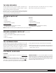
THE NEW SPEAKERS Although Paradigm® Reference in-wall LCR speakers sound great out of the carton, they will sound even better once they are broken in. Operate them for several hours before listening critically. Clean speaker housing with a soft, damp cloth, Do not use a strong or abrasive cleaner or get any part of the speaker wet. High-frquency drivers use ferro-fluid that can thicken at temperatures below 10° C (50° F).
PLACEMENT GUIDELINES (continued) Paradigm® Reference in-wall LCR speakers are designed for use as front Left, Right and Center speakers in a high-end in-wall home theater or music listening application. For homeowners who wish to expand their system to incorporate Surround/Rear speakers, Paradigm® Reference offers a number of state-of-the-art options (see Dealer for more information).
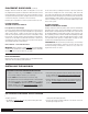
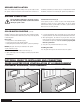
INSTALLING THE BACKBOX (continued) THE MASONITE COVER Leave the masonite cover attached when installing backbox. It prevents dust and dirt from entering the box. Do not remove until ready to install speakers. INSTALLING BX-LCR 3 (backbox) for SA-LCR 3 (speaker) Vertical Installation Horizontal Installation The BX-LCR 3 backbox is designed to fit vertically between two standard 2˝ x 4˝ (or 2˝ x 6˝) wall studs on 16˝ centers. See Fig. 3 for detailed instructions.
SPEAKER INSTALLATION When all the drywall cutting and sanding is done you are ready to install the speakers. Remove the masonite cover and follow the instructions for installation provided for your model in Figs. 9 or 10 (Horizontal or Vertical Installation). Instructions for connecting the speaker are provided below. SPEAKER CONNECTION Turn all amplifier(s) OFF before connecting speakers. This will avoid damage which results from accidental shorting of speaker cables.
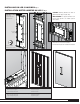
INSTALLING BX-LCR 3 BACKBOX Fig. 3 INSTALLATION BOÎTER ARRIÈRE BX-LCR 3 CUTOUT DIMENSIONS / DIMENSIONS DU TROU (h x w) / (h x l): 21-13/16 in x 8-1/8 in 55.4 cm x 20.6 cm Fig. 3 CAUTION: Mounting brackets are made of galvanized steel. Edges may be sharp. a) MISE EN GARDE: les supports de fixation sont faits en acier galvanisé. Les rebords peuvent être coupants. 13-13/16 in 35.1 cm 2-11/16 in 6.8 cm 2-11/16 in 6.8 cm Box can be rotated Placement for a horizontal installation 8-3/8 in 21.
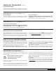
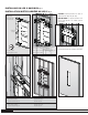
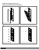
INSTALLING BX-LCR 5 BACKBOX Fig. 4 INSTALLATION BOÎTER ARRIÈRE BX-LCR 5 Fig. 4 CAUTION: Mounting brackets are made of galvanized steel. Edges may be sharp. a) CUTOUT DIMENSIONS / DIMENSIONS DU TROU (h x w) / (h x l): 35-1/2 in x 8-1/8 in 90.1 cm x 20.6 cm MISE EN GARDE: les supports de fixation sont faits en acier galvanisé. Les rebords peuvent être coupants. 4-1/4 in 10.9 cm 4-15/16 in 12.6 cm 13-15/16 in 35.4 cm 4-1/4 in 10.
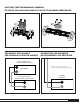
ROTATING TWEETER/MIDRANGE ASSEMBLY ROTATION DES HAUT-PARLEURS DE HAUTE ET MOYENNE FRÉQUENCES SA-LCR 3 SIG-LCR 5 90° 90° Fig. 5 Fig. 6 PRE-WIRING THE BACKBOX CONNECTING THE SPEAKERS PRÉ-CÂBLAGE DU BOÎTIER ARRIÈRE RACCORDEMENT DES ENCEINTES RECEIVER/AMPLIFIER RÉCEPTEUR/AMPLIFICATEUR – Connect for correct polarity. See page 6. Raccordez selon la polarité appropriée. Voir page 19. LEFT FRONT + SPEAKER ENCEINTE LEFT FRONT BACKBOX BOÎTER ARRIÈRE GAUCHE AVANT + Fig. 7 – – + + + + Fig.
INSTALLING SPEAKER VERTICALLY Fig. 9 INSTALLATION VERTICALE DE L’ENCEINTE a) Fig.
INSTALLING SPEAKER HORIZONTALLY Fig. 10 INSTALLATION HORIZONTALE DE L’ENCEINTE a) Fig.
COLOR-MATCH PAINTING (optional) APPARIEMENT DE LA COULEUR (optionnel) Screw quantity varies by model La quantité de vis dépend du modèle Grille Fig. 11 TROUBLESHOOTING GUIDE PROBLEM SOLUTION No Sound Make sure receiver, preamp or amplifier is plugged in and turned on. Check power outlet at the wall is working. Are headphones plugged in, or is system on Mute? Re-check all connections. No Sound from One or More Speakers Check your balance control.
LIMITED WARRANTY Paradigm® Reference in-wall LCR speakers covered in this manual are warranted to be and remain free of manufacturing and/or material defects for a period of five (5) years from the date of original purchase. Within the time period specified, repair, replacement or adjustment of parts for manufacturing and/or material defects will be free of charge to the original owner. Thermal or mechanical abuse/misuse is not covered under warranty.
IMPORTANT! Ces enceintes sont conçues pour les applications de pré-construction installées de façon professionnelle. Elles doivent être installées dans le boîtier arrière ParadigmMD correspondant (vendu séparément). Elles ne sont PAS recommandées pour une application encastrée. MANUEL D’INSTALLATION BOÎTIER ARRIÈRE ET ENCEINTE IN-608 ENCEINTES GCD ENCASTRABLES AU MUR Félicitations! Nous vous remercions d'avoir choisi ces enceintes ParadigmMD Reference.
IMPORTANT! VEUILLEZ LIRE CE QUI SUIT AVANT DE COMMENCER L’INSTALLATION. Respectez tous les codes d’incendie, de sécurité et de construction locaux pendant l’installation. Paradigm NE FOURNIT PAS les vis pour fixer le boîtier arrière sur les montants du mur.
LES NOUVELLES ENCEINTES Bien que les enceintes LCR ParadigmMD Reference offrent un excellent son « en sortant de la boîte », leur son sera encore meilleur après une période de rodage. Les laisser fonctionner pendant quelques heures avant une première écoute critique. enceintes ont été transportées ou entreposées au froid, les laisser réchauffer à la température de la pièce avant de les utiliser. Nettoyer les boîtiers à l’aide d’un linge doux et humide.
POSITIONNEMENT (suite) Vous trouverez ci-dessous quelques directives pour obtenir un son optimal dans n’importe quelle pièce : Comme canal central, une enceinte LCR sur le mur ParadigmMD Reference permettra aux auditeurs dans l’ensemble de la pièce d’entendre les dialogues, les effets sonores et la musique avec une clarté et une intelligibilité optimales.
INSTALLATION DU BOÎTIER ARRIÈRE (suite) POURQUOI UN BOÎTIER ARRIÈRE L’installation de ces enceintes dans les boîtiers arrière ParadigmMD correspondants a de nombreux objectifs : • Le boîtier est conçu pour fournir un volume optimal, ce qui améliore la qualité du son et diminue la distorsion. • Le boîtier arrière est un support nécessaire pour le cadre de montage de l’enceinte et le montage de l’écran acoustique.
PRÉ-CÂBLAGE DU BOÎTIER ARRIÈRE (Fig. 7) Vous êtes maintenant prêt à effectuer le filage préalable du boîtier arrière pour l’installation ultérieure de l’enceinte. Pour une reproduction optimale du son, il est essentiel d’utiliser des câbles d’enceinte de haute qualité. N'utilisez que des câbles cotés pour une utilisation dans des murs : • Les câbles de types CL2, CL3 et CM sont conformes à la norme UL. • Les câbles de type FT4 sont conformes à la norme CSA.
GUIDE DE DIAGNOSTIC PROBLÈME SOLUTION Aucun son S'assurer que le préamplificateur ou l'amplificateur est branché et allumé. Vérifier que la prise de courant fonctionne correctement. Des écouteurs sont-ils branchés ou le système est-il en mode sourdine (mute)? Vérifier tous les raccords. Aucun son d'une ou de plusieurs enceintes Vérifier la commande de réglage d'équilibre (balance) ou la commande de volume VC 150 (si elle est utilisée).
NOTES
NOTES
NOTES
w w w . p a r a d i g m . c o m © PARADIGM ELECTRONICS INC.