THE ULTIMATE IN HIGH-END SOUND FOR MUSIC AND HOME THEATER ™ OWNERS MANUAL OM-1000 STUDIO AND SIGNATURE SERIES: FRONT AND CENTER-CHANNEL SPEAKERS Thank you for choosing Paradigm® Reference speakers and congratulations! You are about to experience the stunning difference that these state-of-the-art high-end speakers will make in your music and home theater system.
TABLE OF CONTENTS Your New Speakers . . . . . . . . . . . . . . . . . . . . . . . . 2 Speaker Placement . . . . . . . . . . . . . . . . . . . . . . . 11 Unpacking Instructions (Pictorial) . . . . . . . . . . . . 3 Wall Mounting . . . . . . . . . . . . . . . . . . . . . . . . . . . 12 Speaker Placement and Connection (Pictorial) . . 4 Speaker Connection . . . . . . . . . . . . . . . . . . . . . . 12 Bracket Installation for On-Wall Speakers (Pictorial) . . . . . . . . . . . . . . . . . . . . . . . .
UNPACKING INSTRUCTIONS (pictorial) (if included with your model) 3
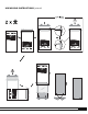
SPEAKER PLACEMENT AND CONNECTION (pictorial) Fig. 1 Fig. 1a Fig. 1b Fig. 3 Fig. 2 4 Fig.
Fig. 5a For Center Channels with Outrigger Feet Fig. 5b For Center Channels with Cradles USE OF THIS TILT BRACKET IS RECOMMENDED, BUT OPTIONAL Note: Bracket not for use with a Paradigm Stand STEP 1 Remove grille. To prevent scratching the finish, carefully lay the speaker on a blanket or soft drop cloth with cradles positioned for easy access, as shown. STEP 3 Push down firmly with both thumbs where indicated (see inset) and bracket will snap into place. Repeat steps 1 to 3 for second bracket.
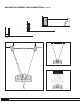
SPEAKER PLACEMENT AND CONNECTION (pictorial) cont’d. Hidden cable channel Fig.
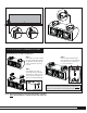
Fig. 7a Fig. 7b Fig.
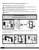
BRACKET INSTALLATION FOR ON-WALL SPEAKERS (pictorial) IMPORTANT NOTES: Please read before installing brackets Paradigm DOES NOT supply hardware for mounting brackets to the wall. Mounting hardware shown is an example only; hardware will vary depending on wall type. If installing in drywall, thickness should be 1/2˝ (13 mm) or 5/8˝ (16 mm) only. Screws must be long enough to go through anchor bolts and firmly into drywall (see Inset 1).
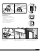
Fig. 8e ADJUST BRACKETS TO ACHIEVE DESIRED ANGLE OF TILT: a) Tilt speakers inward for better imaging; b) Tilt center speaker up or down to optimize clarity and intelligibility or; c) Mount speaker parallel to the wall (horizontally or vertically), using bracket at the 0° position. Align screws with desired angle position (refer to information at far right) and screw in. Minimum clearance between edge of TV and center of bracket is 6-7/8˝ (175 mm) Minimum clearance 6-7/8˝ (175 mm) Fig. 8f Fig.
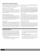
PREVENTING SPEAKER DAMAGE Paradigm® Reference speakers are efficient and can be driven to loud listening levels with moderate amplifier power. They are also able to handle the output of very powerful amplifiers. To prevent damage to your speakers, please read the following guidelines before hooking them up. Amplifier Distortion – The #1 Culprit! Amplifier distortion is the principal cause of speaker damage. When listening at loud levels your amplifier may run out of clean power.
SPEAKER PLACEMENT FRONT SPEAKERS (Left/Right) Paradigm® Reference front speakers are designed to allow flexible placement while providing a very large window of sound throughout your listening room. To ensure the best high-end performance possible however, we strongly recommend that you observe the following placement guidelines: Accurate Timbre (Fig. 1) For the most accurate and natural timbre, place Paradigm® Reference Front speakers so that their high-frequency drivers are approximately at ear level.
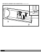
ATTACHING THE TV-TOP/SHELF SUPPORT (Fig. 6) Your On-Wall Center-Channel speaker can also be placed on top of a TV, or on a shelf using the TV-Top/Shelf Support included. IMPORTANT! If you are placing your speaker on top of a TV or shelf, for stability you must use the TV-Top/Shelf Support included. 2. Using the two screws (included) attach Support to the back of the speaker. 3. Apply self-adhesive rubber pads (included) to bottom of speaker, as shown, so that speaker sits securely and cannot slip. 4.
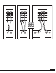
This section outlines other connection options. DO NOT attempt to bi-wire or bi-amplify unless you have removed the jumper bars. Bi-wire Connection (Fig. 7b) Bi-wiring can improve clarity and openness, with less grain and more solidity to the bass. Two cables are required for each speaker that you bi-wire. Bi-amp Connection (Fig. 7c) Passive bi-amping offers a dramatic improvement in clarity, openness and detail, with much better bass solidity and definition.
LIMITED WARRANTY Paradigm® Reference speakers covered in this manual are warranted to be and remain free of manufacturing and/or material defects for a period of five (5) years from the date of original purchase. Within the time period specified, repair, replacement or adjustment of parts for manufacturing and/or material defects will be free of charge to the original owner. Thermal or mechanical abuse/misuse is not covered under warranty.
NOTES 15
NOTES 16
LE SUMMUM EN QUALITÉ SONORE HAUT DE GAMME POUR LA MUSIQUE ET LE CINÉMA MAISON MC MODE D’ EMPLOI OM-1000 SÉRIES STUDIO ET SIGNATURE : ENCEINTES AVANT GAUCHE ET DROITE ET ENCEINTE CENTRALE Félicitations! Nous vous remercions d'avoir choisi les enceintes de la série ParadigmMD Reference. Vous allez entendre la différence que confèrent ces enceintes de pointe haut de gamme à votre système audio ou de cinéma maison.
TABLE DES MATIÈRE Vos nouvelles enceintes . . . . . . . . . . . . . . . . . . . . . 2 Positionnement des enceintes. . . . . . . . . . . . . . . 11 Instructions de déballage (figures) . . . . . . . . . . . . 3 Installation au mur . . . . . . . . . . . . . . . . . . . . . . . . 12 Positionnement et raccordement des enceintes (figures) . . . . . . . . . . . . . . . . . . . . . . . . . . 4 Raccordement des enceintes . . . . . . . . . . . . . . . .
INSTRUCTIONS DE DÉBALLAGE (figures) (si compris avec votre modèle) 3
POSITIONNEMENT ET RACCORDEMENT DES ENCEINTES (figures) Fig. 1 Fig. 1a Fig. 1b Fig. 3 Fig. 2 4 Fig.
Fig. 5a Pour canaux centraux avec pieds stabilisateurs Fig. 5b Pour canaux centraux avec supports L’UTILISATION DU SUPPORT INCLINABLE EST RECOMMANDÉE, MAIS FACULTATIVE Remarque : le support ne doit pas être utilisé avec un pied Paradigm ÉTAPE 3 Appuyez fermement avec les deux pouces sur l’endroit indiqué (voir l’encart – ‘PUSH HERE’) et le support s’enclenchera fermement. Répétez les étapes 1 à 3 pour le deuxième support. ÉTAPE 1 Enlevez la grille.
POSITIONNEMENT ET RACCORDEMENT DES ENCEINTES (figures) suite Conduit de câble caché Fig.
Fig. 7a Fig. 7b Fig.
INSTALLATION DU SUPPORT POUR LES ENCEINTES MURALES (figures) REMARQUES IMPORTANTES : Veuillez lire ces directives avant d’installer les enceintes murales Paradigm NE FOURNIT PAS le matériel pour monter les supports sur le mur. Le matériel de montage illustré est uniquement un exemple; il variera selon le type de mur. Si vous effectuez l’installation dans une cloison sèche, l’épaisseur doit être de 1/2 po (13 mm) ou de 5/8 po (16 mm) uniquement.
Fig. 8e RÉGLEZ LES SUPPORTS POUR OBTENIR L’ANGLE D’INCLINAISON SOUHAITÉ : a) Incliner les enceintes vers l’intérieur pour une meilleure imagerie; b) Incliner l’enceinte du centre vers le haut ou vers le bas pour optimiser la clarté et l’intelligibilité; c) Monter l’enceinte en parallèle au mur (horizontalement ou verticalement) ; utilisez le support en position 0°. Alignez les vis selon l’angle souhaité (consultez les renseignements à droite) et vissez.
POUR EVITER D'ENDOMMAGER LES ENCEINTES Les enceintes ParadigmMD Reference sont efficaces et peuvent produire des volumes élevés à des puissances de sortie modérées de l’amplificateur. Elles peuvent également être jumelées à des amplificateurs haute puissance. Pour éviter d’endommager les enceintes, lire les directives suivantes avant de procéder à leur raccordement.
POSITIONNEMENT DES ENCEINTES ENCEINTES AVANT (gauche/droite) Les enceintes avant gauche/droite de ParadigmMD Reference sont conçues pour offrir une grande souplesse dans le choix de leur emplacement tout en produisant une très vaste courverture sonore dans toute la salle d’écoute. Pour la meilleure performance possible, il est toutefois recommandé de suivre les directives suivantes sur le positionnement des enceintes. Précision du timbre sonore (Fig. 1) Image optimale (Fig.
FIXATION DU SUPPORT POUR TÉLÉ/ÉTAGÈRE (Fig. 6) L’enceinte centrale au mur peut aussi être placée sur une télévision ou une étagère à l’aide du support pour télé/étagère inclus. IMPORTANT! Pour l’installation de l’enceinte sur une télé ou une étagère, utiliser le support pour télé/étagère inclus pour une stabilité accrue. 2. À l’aide des deux vis (incluses), fixer le support au dos de l’enceinte. 3.
Raccordement standard des enceintes avec 2 bornes (Fig. 7a) Laisser les barrettes de connexion en place et connecter les conducteurs du câble sur l’une ou l’autre des paires de bornes. On peut effectuer le branchement sur les bornes de l’enceinte avec cosses en fourche, fiches banane ou connecteurs à broche, ou même avec le fil nu. Serrer la vis de serrage de chaque borne à la main, fermement mais sans excès. La section suivante décrit les autres options de raccordement.
GUIDE DE DIAGNOSTIC PROBLÉME Aucun son Aucun son d'une ou plusieurs enceintes Déficience des graves ou image disloquée SOLUTION S'assurer que le préamplificateur ou l'amplificateur est branché et allumé. Vérifier que la prise de courant fonctionne correctement. Les écouteurs sont-ils branchés ou le système est-il en mode sourdine (mute)? Vérifier tous les raccords. Vérifier la commande de réglage d'équilibre (balance) ou la commande de volume VC-150 (si elle est utilisée).
NOTES 15
NOTES 16