Mini Compact Outdoor Solid State Power Amplifier Operations Manual Paradise Datacom LLC 328 Innovation Blvd. State College, PA 16803 USA Email: sales@paradisedata.com 208143 REV - Phone: (814) 238-3450 Fax: (814) 238-3829 Web: www.paradisedata.
© 2010 Paradise Datacom LLC Printed in the USA 2 208143 REV - Operations Manual, HPA3, Mini Compact Outdoor SSPA
Table of Contents Table of Contents .................................................................................................................. 3 Section 1: General Information ............................................................................................ 9 1.0 Introduction ............................................................................................................. 9 1.1 Description ........................................................................................
3.2.3 Quick Start RS-232 Connection .............................................................. 27 3.3 Universal M&C Operation ..................................................................................... 28 3.3.1 Universal M&C Status Window................................................................ 29 3.3.1.1 Signal Indicators ........................................................................ 29 3.3.1.2 Fault Status Indicators ..........................................................
Section 6: Maintenance and Troubleshooting .................................................................. 53 6.0 Introduction ........................................................................................................... 53 6.1 Cooling System Maintenance ............................................................................... 53 6.2 Fan Removal and Heatsink Cleaning.................................................................... 53 6.2.1 Fan Replacement...........................
Figures Figure 2-1: Outline Drawing, Ku-Band Mini Compact Outdoor SSPA .................................... 13 Figure 2-2: Mini Compact Outdoor SSPA Air Flow ................................................................ 19 Figure 2-3: Attach Mounting Supports to Unit ........................................................................ 21 Figure 2-4: Install All-Thread stud ..........................................................................................
Tables Table 2-1: Unit weights (typical) ............................................................................................ 14 Table 2-2: J4 Monitor & Control Port Pin-Outs ...................................................................... 16 Table 2-3: J5 Link Port Pin-Outs ............................................................................................ 17 Table 2-4: J6 Switch Port Pin-Outs ........................................................................................
THIS PAGE INTENTIONALLY LEFT BLANK 8 208143 REV - Operations Manual, HPA3, Mini Compact Outdoor SSPA
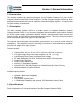
Section 1: General Information 1.0 Introduction This section provides the general information for the Paradise Datacom LLC line of Mini Compact Outdoor Solid State Power Amplifiers. The Mini Compact Outdoor SSPA has been designed and manufactured to be an extremely robust and reliable amplifier. It is well suited for harsh outdoor environments. 1.1 Description The Mini Compact Outdoor SSPA is a smaller version of Paradise Datacom’s popular Compact Outdoor SSPA.
1.3 Inspection When the unit is received, an initial inspection should be completed. First ensure that the shipping container is not damaged. If it is, have a representative from the shipping company present when the container is opened. Perform a visual inspection of the Compact Outdoor Amplifier to make sure that all items on the packing list are enclosed.
• • • • Always terminate the RF input and output connector prior to applying prime AC input power. Never look directly into the RF output waveguide Maintain a suitable distance from the source of the transmission such that the power density is below recommended guidelines in ANSI/IEEE C95.1. The power density specified in ANSI/IEEE C95.1-1992 is 10 mW/cm2. These requirements adhere to OSHA Standard 1910.97.
THIS PAGE INTENTIONALLY LEFT BLANK 12 208143 REV - Operations Manual, HPA3, Mini Compact Outdoor SSPA
Section 2: Installation 2.0 Introduction This section provides a physical description of the Mini Compact Outdoor, including pin-outs of all connectors, power requirements for the installed unit, and instructions on single-unit boom mounting. 2.1 Dimensions and Weight ETHERNET READY The Mini Compact Outdoor SSPA enclosure dimensions are 9.00 in. W x 12.00 in. L x 8.00 in. H.
Table 2-1: Unit weights (typical) Model Number Weight Units HPACC3075AC_XXXX 26.0 (11.8) lbs. (kg) HPACC3100AC_XXXX 26.0 (11.8) lbs. (kg) HPAXX3050AC_XXXX 25.5 (11.6) lbs. (kg) HPAXX3075AC_XXXX 25.5 (11.6) lbs. (kg) HPAXX3100AC_XXXX 25.5 (11.6) lbs. (kg) HPAXX3175AC_XXXX 25.5 (11.6) lbs. (kg) HPAKU3050AC_XXXX 24.5 (11.1) lbs. (kg) HPAKU3080AC_XXXX 24.5 (11.1) lbs. (kg) 2.
2.2.3 RF Output Sample Port (J3) [Type N (F)] The RF Output Sample port, J3, is located on the bottom of the amplifier as shown in Figure 2-1. This connector provides a -40 dBc coupled sample of the amplifier’s output signal. It is a type N female connector. 2.2.4 Monitor & Control Port (J4) [MS3112E18-32S] The M&C (Monitor and Control) connector is the primary input for controlling the amplifier and monitoring fault conditions. It is a 32-pin circular connector, MS3112E18-32S.
Table 2-2: J4 Monitor & Control Port Pin-Outs Pin # 16 Signal Type B Mute Input Unit powers up muted. This line Closure to Ground Disables DC power to SSPA must be pulled to ground (V or d) to enable amplifier.
2.2.4.2 Serial I/O Control (J4) For serial data control of the Compact Outdoor SSPA, a Windows-based Monitor &Control program is supplied with the amplifier that allows all of the control and alarm functionality over a serial communication link. Both RS-232 and RS-485 can be used to communicate with the amplifier. The amplifier default is to operate on RS-485 but can easily be set to RS-232 by pulling the RS-232/ RS-485 Select line low. This is done by connecting J4-Pin D to J4-Pin V.
2.2.7 AC In (J7) [MS3102R16-10P] The Prime power connector is a 3-pin circular connector, J7. The power supplies provide universal AC input by using auto-sensing power supplies. The AC input can operate over a range of 85-265 VAC, at 47 to 63 Hz. The power supply is also power factor corrected, enabling the unit to achieve a power factor greater than 0.95. The AC Line input connector configuration is given in Table 2-5.
2.2.9 Chassis Ground Pin A Chassis ground terminal is provided on the bottom side of the amplifier. A ¼ - 20 threaded terminal is provided for equipment grounding. 2.3 Physical Features In addition to the I/O connectors, the Mini Compact Outdoor user-friendly features include a summary alarm indicator and a removable fan tray. 2.3.1 Summary Alarm Indicator A summary alarm indicator LED is located on the input side of the amplifier. When the SSPA is online, this indicator illuminates GREEN.
Warning! The Mini Compact Outdoor SSPA should NEVER be mounted with the fans facing up. Doing so will void your warranty. The fans should be examined periodically and any obstruction or debris should be cleared. Inadequate air flow can cause the amplifier to overheat and cause a temperature fault. See Section 6: Troubleshooting and Maintenance for cleaning instructions. 2.
2.4.3 Installation ETHERNET READY 1. Cut gasket (Item 8) into four (4) 1.5” x 7” pieces. Attach gasket to each support bracket (Item 1) as shown in Figure 2-3. Trim gasket around bottom corners and slot in bracket. 2. Locate the mounting studs on the bottom of the Mini Compact Outdoor SSPA unit. Using a 1/2” bolt (Item 7), two flat washers (Item 6), and a 1/2” nut (Item 5), firmly bolt one mounting bracket to each mounting stud, as shown in Figure 2-3.
ETHERNET READY 4. Bring the unit up tight under the boom (with the long axes parallel), sliding the All-Thread studs past the sides of the boom to show above the boom top. Place the remaining pieces of Uni-Strut (Item 2) open channel down across the boom onto the protruding All-Thread stud ends. Secure firmly with a flat washer (Item 6), lock washer (Item 4) and 1/2” nut (Item 5) on each of the four All-Thread stud ends. Looking from the end of the boom, the mounted unit should look as shown in Figure 2-5.
Section 3: Quick Start and Operation 3.0 Introduction The Mini Compact Outdoor SSPA is available with a standard Ethernet & RS232/485 interface. This section summarizes the connections to a remote computer for various remote communications. Table 3-2 summarizes the hardware connections of Port J4 for all remote communication connections. 3.0.1 Remote Communications Connections Units can be configured for either Ethernet (default IP or user-defined IP), RS-485, or RS-232 communications.
Chassis Ground V TX Enable B Interface Select 0 e Interface Select 1 j RS232/RS485 Select D Isolated Return for RS232/RS485 d RS485 (RX-) RS232 (RX) F RS485 (TX-) RS232 (TX) E RS485 (TX+) T RS485 (RX+) U J4 Figure 3-3: J4 Connections for RS-485 Communications Chassis Ground V TX Enable B Interface Select 0 e Interface Select 1 j RS232/RS485 Select D Isolated Return for RS232/RS485 d RS232 (RX) F RS232 (TX) E J4 Figure 3-4: J4 Connections for RS-232 Communications 3.
Units may ship with a RS-232 Quick Start cable fitted with a DB9 connector. See Figure 3-6. Figure 3-6: RS232 Quick Start Cable, 207988 3.2 Quick Start Operation This section describes the necessary steps to communicate with a Mini Compact Outdoor SSPA using the Ethernet Quick Start cable and the Universal M&C Software. The Paradise Datacom Universal M&C Software is a free Windows-based application that can be downloaded from the company web site, www.paradisedata.com.
If using Windows 7 or Windows Vista: 1. 2. 3. 4. 5. 6. Click on the Windows icon in the lower left corner and select Control Panel; Click on the Network and Sharing Center link; Click on the Local Area Connection link; Click on the Properties button; Select Internet Protocol Version 4 (TCP/IP v4) and click on the Properties button; Select “Use the following IP address” and enter the following information: IP address: 192.168.0.1 Subnet mask: 255.255.255.0 6.
3.2.3 Quick Start RS-232 Connection The following steps outline how to quickly connect to your Mini Compact Outdoor SSPA using the RS-232 Quick Start cable. 1. 2. 3. 4. Unpack the amplifier and connect the RF Input and RF Output. Ensure the J1 RF Output port is properly terminated. Connect the AC input power to connector J7. When shipped from the factory, the Mini Compact Outdoor SSPA is set to start up muted. 5.
3.3 Universal M&C Operation 1. Run the Paradise Datacom Universal Monitor and Control Program from the Programs Menu of your PC. 2. Select [Action] → [Add Unit] from the main menu of the Universal M&C Program and select [Mini Compact Outdoor SSPA] from the menu choices. See Figure 3-7. Figure 3-7: Universal M&C Add Unit menu 3. A new dialog window will open (see Figure 3-8).
1 5 4 3 6 2 Figure 3-9: Universal M&C Status Window 3.3.1 Universal M&C Status Window The Universal M&C Software will initialize and open to the Status Window, the main monitoring display. See Figure 3-9. The Status Window shows the the current conditions (or state) of the Compact Outdoor SSPA. In addition, the status screen allow the user to alter the Mute condition of the carrier and adjust the on-board Attenuator for gain control.
3.3.1.2 Fault Status Indicators The Fault Status frame in the lower left side of the Status Window contains a grid of SSPA fault indicators. See Figure 3-9, Item [2]. A green indicator signifies proper operation; red signifies a fault condition. Summary Alarm: The Summary Alarm is simply a logical ‘OR’ of any of the alarm indicators. Unit Online: The Unit Online indicator is relevant in redundant systems. If the unit is clear of faults and active, the indicator will be green.
3.3.1.3 Voltage, Current and Temperature Display On the right side of the Status window there is a thermometer display that reports the present temperature of the amplifier. See Figure 3-9, Item [3]. A 20-30°C rise above ambient temperature is typical. To the left of the thermometer display are several indicators that show various operating conditions of the Compact Outdoor Amplifier in real time.
3.3.2 Universal M&C Settings Window Figure 3-10 shows the ‘Settings’ window of the Paradise Datacom Universal M&C Software. The ‘Settings’ window contains many of the global settings that are available in the SSPA. 1 2 12 3 4 IPNET 5 6 7 8 13 9 10 11 Figure 3-10: Universal M&C, Settings Power Up Settings The Mini Compact Outdoor amplifier will power up with the “last-state” settings before the unit was powered down.
rate is 9600. You will be asked to verify that you wish to change the Baud Rate. Communication with the amplifier may be affected. [7] Standby Mode: Selects between Hot and Cold standby mode for units in redundant systems. [8] BUC Reference: Selects between an Internal or External reference for an optional block up coverter integrated with the unit, or allows the unit to Autoswitch between Internal and External reference.
[13] Fault Setups: The user may also adjust the Spare, Auxiliary, BUC, Fiber, and Forward RF Fault Status and Handling via the appropriate pull-down menus on the Settings Window. [Type] Fault Handling: Selects whether the associated fault should be a major or minor fault, and whether the fault should mute the unit. A minor fault will trigger a Spare/Auxiliary/BUC/Forward RF Fault alarm but not trigger a Summary Fault.
3.3.4 Universal M&C Preferences The user can adjust certain preferences of the Universal Monitor and Control Software. See Figure 3-13. Figure 3-13: Preferences Window Queries: Enable and adjust the interval that the software queries the unit. Note that if queries are disabled, there will be no communication with the unit at startup. Logs: Enable and adjust the interval that the software writes to the log. The log location is determined during unit setup.
3.4 Web-based M&C The most basic method of communication with the Mini Compact Outdoor SSPA is via a web browser, which accesses the built-in web pages served from the amplifier’s embedded web server. Supported web browsers include Internet Explorer version 6 or better, and Mozilla Firefox version 3.0.3 or better.
As the applet loads, the user will be prompted to enter a password. The default password is paradise (see Figure 3-17), but the user may assign a new password using the web M&C or Paradise Datacom’s Universal M&C Software. See Section 3.3 for details on using the Universal M&C Software. Figure 3-17: Enter password (default is “paradise”) 3.4.1 Navigating the Web M&C The SSPA Monitor and Control is performed via following the links on the web page.
Select Protocol: Serial, IPNet or SNMP. Choose Baud Rate: 2400, 4800, 9600, 19200 or 38400 Enter relevant IP Settings for user’s network; Click ‘Change IP’ button to change. Click ‘Read IP’ button to populate current IP settings. Enter a new Web Password; Click ‘Change’ to set. Enter new Read/Write Community password; Click button to change. Figure 3-19: Communication Settings window descriptions • Communication Settings Window: Read/Write listing of adjustable SSPA communication parameters.
Select Mute State: Muted or Unmuted. Select Single or Redundant Mode. Select BUC Source Reference: Internal, External, Auto. Select HPA1 or HPA2. Select Startup State: Online or Standby. Select Attenuation; Click ‘Change’ to set. Select Standby Mode: Hot or Cold Standby. Select Network Address; Click ‘Change’ to set. Figure 3-20: General Settings window descriptions • General Settings Window: Displays the SSPA Redundancy and BUC/Amplifier Settings.
Select “Ignore”, “Fault on High”, “Fault on Low”, “10% Window” or “15% Window”. Select “Minor Fault”, or “Major Fault”. Select “Ignore”, “External Mute”, “Reference Level” or “LNB Current”. Select Forward RF Fault Threshold. Click “Change”. Select “Minor Fault”, “Major Fault” or “Major Fault + Mute”. Select High Temp. Threshold. Click “Change”. Select Minimum and Maximum Values; Click ‘Change’ to set. Select “Ignore”, “LogicHigh” or “LogicLow”.
Section 4: L-Band Operation 4.0 Block Up Converter Overview The Mini Compact Outdoor SSPA is available with various converter options, utilizing Paradise Datacom’s integrated converter. The primary up converter option is offered in two C-Band configurations, two Ku-Band options, and one X-Band model. The BUC offers ultra low phase noise for applications where phase noise is an overriding factor. For specifications, see Table 4-1.
Block Up Converter Module SSPA Module 55 - 75 dB Gain L Band Input DeMux Reference Input Optional FSK Phase Locked Local Oscillator Optional Internal Reference FSK Optional FSK Monitor & Control Figure 4-2: Compact Outdoor Block Diagram of BUC / SSPA System Note: Unless the BUC has the built-in internal reference option, if there is an absence of a 10 MHz reference signal on the IFL input there will be no output signal from the SSPA. 4.
4.2 Theory of Operation The low gain block up converter has a P1dB of 0dBm. This topology allows the system to be integrated with little impact on the general electrical specifications of the SSPA module. The converter utilizes single up conversion from L-Band to the desired RF band. The local oscillator circuits are designed to maintain the lowest possible output phase noise.
Notes: 1) The external reference option requires the system operator to provide system reference to the BUC/SSPB. The system will not lock and will have no output without external reference applied. 2) Internal reference option allows for either internal or external reference operation.
4.5 Typical System Configuration This section shows the Compact Outdoor SSPB in a common system application. Figure 4-3 shows the Compact Outdoor used with a Paradise Datacom Evolution Series PD25 modem. Indoor Equipment Outdoor Equipment PARADISE DATACOM IFL Cable RS485 M&C IF: 950 - 1450 MHz (-30 to -20 dBm ) at Compact Outdoor SSPB Ref: 10 MHz (-5 dBm to +5 dBm) at Compact Outdoor SSPB Figure 4-3: Mini Compact Outdoor SSPB with PD25 Evolution Modem 4.
THIS PAGE INTENTIONALLY LEFT BLANK 46 208143 REV - Operations Manual, HPA3, Mini Compact Outdoor SSPA
Section 5: Performance Tests 5.0 Introduction This section describes some of the tests performed on production amplifiers before shipment. Where possible, Paradise Datacom LLC maintains computer automated RF test stations to ensure a high level of accuracy and consistency to production amplifier testing. 5.1 Standard tests All Paradise Datacom Compact Outdoor amplifiers must meet rigid specifications and undergo the following tests.
5.1.2 Spurious Spurious signals are undesirable byproducts of amplifiers caused by nonlinearities within the amplifier and other system level components such as switch mode power supplies. These unwanted signals cause signal management problems in system applications. Out of band spurious signals cause interference to other pieces of equipment. See Figure 5-1, Item [2]. 5.1.3 Input Return Loss The input return loss is measured in all production amplifiers.
5.1.5 Intermodulation Distortion Intermodulation distortion is one of the most important characteristics of a Solid State power amplifier system. Satellite communication systems must comply to certain distortion levels depending on the service involved. All production amplifiers are subjected to automated intermod testing. This is based on a standard two-tone intermod test in which the intermod level (IMD) is measured in dBc with respect to the main tones and the highest third order intermod products.
5.1.7 Earth Ground This test measures the leakage current and verifies that each pin on J8 is connected correctly. See Figure 5-3, Item [1]. 5.1.8 Sample Port The RF Sample Port is measured at discrete frequencies across the band and a calibration label is placed near the Type N connector on the bottom of the unit. The sample port is approximately -40 dB from the RF output level. A label with the exact coupling ratio is attached to the amplifier chassis. See Figure 5-3, Item [2]. 5.1.
5.2 Tests for units with integrated BUC If the Compact Outdoor amplifier includes a block up converter (BUC), the following tests are included. 5.2.1 Reference Lock This test checks the external/internal references (if equipped), as well as lowest locking level at 10 MHz. See Figure 5-3, Item [5]. 5.2.2 FSK Verifies FSK communication with the BUC. See Figure 5-3, Item [6]. 5.2.3 Phase Noise Tests phase noise using external and internal (if equipped) references.
5.3 Optional Tests The following tests are performed on units at the request of the customer, usually to verify specific customer requirements. 5.3.1 Noise Figure Using a noise figure meter, the unit is tested to verify it operates within specification. 5.3.2 Group Delay The testing software measures the linear, parabolic, and ripple components to verify the unit is within specification. 5.3.3 AM/PM The testing software measures the slope of the amplifier’s insertion phase vs. output power. 5.3.
Section 6: Maintenance and Troubleshooting 6.0 Introduction This section describes some of the standard maintenance practices that can be performed on the Mini Compact Outdoor Amplifier and tips to troubleshoot common customer issues. 6.1 Cooling System Maintenance It is recommended that the cooling system be checked at least once per month. This involves visually inspecting the fan intakes to make sure that there is no obstructions over the intake.
6.3 Troubleshooting guide The following section describes solutions for some of the most common issues with the operation of the Mini Compact Outdoor SSPA. 6.3.1 Unit doesn’t power up Cooling fans do not spin, and alarm LED lamps are off. Possible causes: AC power is off; Unit is connected to an inadequate circuit breaker. Unit has no connection between chassis and earth ground or has inadequate earth ground. Possible solutions: Check SSPA unit datasheet for AC power requirements.
Possible solutions: a) In the case where SSPA communication settings have been accidentally set to a random configuration, establish a connection to the unit with a L207755 Quick Start cable in conjunction with the Universal M&C software (see Section 3.2.2.2).
THIS PAGE INTENTIONALLY LEFT BLANK 56 208143 REV - Operations Manual, HPA3, Mini Compact Outdoor SSPA
Section 7: Redundant System Configurations 7.0 Redundant System Concepts The Mini Compact Outdoor Amplifier is capable of operating in a variety of redundant system configurations. These include 1:1 and 1:2 as well as 1:1 with L-Band Block Up Converters. The Mini Compact Outdoor Amplifier has a built-in 1:1 redundancy controller, allowing it to be used in 1:1 redundant systems without a separate external controller. When used in a 1:2 redundant system a separate RCP2-1200 controller is required. 7.
The system shown in Figure 7-3 uses the same concept of the power splitter on the RF input. In this case the Compact Outdoor amplifiers are equipped with L-Band block up converters. L-Band input amplifiers use phase locked oscillators as the local oscillator to the up converter. Such systems must use a splitter at the input instead of a switch so that the reference input is always available to the standby amplifier.
Section 8: Remote Control Interface 8.0 Serial Protocol Overview The Mini Compact Outdoor SSPA can be managed and controlled over a variety of remote control interfaces (see Figure 8-1). Remote control interface stack 10Base-T IP Interface SNMP HTTP Web UDP Serial Interface Protocols: 1. Normal 2.
The selected interface is controlled by a combination of internal SSPA settings and/or Interface control pins: Baud1 (Pin e) and Baud0 (Pin j) on the J4 M&C connector (See Table 8-1). Table 8-1: Interface Selection Baud0 (Pin j) state Baud1 (Pin e) state Selected interface Open Open Interface selected by Internal SSPA settings Closure to Chassis ground Open Interface is forced to Ethernet interface. IP address is fixed to 192.168.0.9.
8.1 Serial communication This section describes the normal communication protocol between the Mini CO SSPA and a host computer over RS232/RS485 serial interface. Serial port settings on the host computer must be configured for 8 bit data at no parity, with 1 stop bit. The baud rate should match the selected baud rate parameter on the SSPA unit. Selection between the RS232 and RS485 interface depends on the state of pin D of the J4 M&C connector. Connect pins D and d to select RS232 interface.
8.1.1.3 Source Address The source address specifies the address of the node that is sending the packet. All unique addresses, except the broadcast address, are equal and can be assigned to individual units. The host computer must also have a unique network address. 8.1.2 Data Packet The data sub-packet is comprised of 6 to 32 bytes of information. It is further divided into seven fields as shown in Figure 8-4. The first six fields comprise the command preamble while the last field is the actual data.
varies by the amount of attached data bytes. It may contain 11+N bytes where N is the amount of requested data bytes from a particular table, specified in Data Length field. The Set Request command allows the sender to actively change parameters for the receiver’s internal configuration. The Set Request frame must contain a number of bytes in the Data Field as specified in Data length field. The frame size must be 11+N bytes, where N is the length of the attached data structure.
8.1.2.5 Data Address / Error Status / Local Port Frame Length This field is a tag extension byte and specifies the first table element of the tagged data. If the Data Length is more than 1 byte, then all subsequent data fields must be accessed starting from the specified address. For example, if the requestor wants to access the amplifier’s unique network address, it should set data tag 0 (System settings tag) and data address 8 (see System Settings Details table).
8.1.3 Trailer Packet The trailer component contains only one byte called the Frame Check Sequence. This field provides a checksum during packet transmission. See Figure 8-5. HEADER (4 bytes) DATA (6-32 bytes) TRAILER (1 byte) Frame Check Checksum (1 byte) Figure 8-5: Trailer Sub-Packet 8.1.3.1 Frame Check This value is computed as a function of the content of the destination address, source address and all Command Data Substructure bytes.
8.1.5 Serial Communications Protocol Tables 8-5 through 8-9 describe the various values of the serial communications protocol.
Table 8-7: System Settings Data Values Data Address # Bytes Description Limits and Byte Values 1 1 System Operation Mode Single Amplifier = 255 1:1 Redundant = 0 2 1 System Hierarchical Address Unit 1= 0; Unit 2= 255 3 1 Unit Start Up State (in Redundancy) On Line Amplifier = 255 Standby Amplifier = 0 4 1 Mute State 5 1 Attenuation Level (dB down from maximum gain) Mute Clear (Transmit Enable) = 255 Mute Set (Transmit Disable) = 0 [1 bit for every 0.
Table 8-7: System Settings Data Values (continued) Data Address # Bytes Description Limits and Byte Values 23 1 Forward RF Fault Handling Minor Fault = 255 Major Fault = 0 24 1 Forward RF Fault Handling 0-80 dBm. Value used as Low, Window center point, or High Threshold, depending on Forward RF Fault status setting 25 1 Reserve Reserve 26 1 Reserve Reserve 27 1 Reserve Reserve 28 1 Reserve Reserve 29 1 IP Address Byte 1 (MSB) Default IP Address = 192.168.0.
Table 8-9: System Condition Addressing Data Address # Bytes 1 2 2 2 3 2 Description Attenuation DAC value (Read Only in Temp Co Mode) Present Temperature Fault, Mute, and State Conditions 4 2 Present Attenuation Level 5 2 Present RF Power Level Output is dBm x 10 6 2 Total DC Current 7 2 PS2 Regulator DC Voltage 8 2 PS2 Voltage 9 2 Transistor Gate Voltage 10 11 12 13 14 2 2 2 2 2 15 2 PS1 DC Current PS1 Regulator DC Voltage PS1 Voltage External Reference Level Baseplate Tempe
8.2 Ethernet Interface 8.2.1 Overview The Mini CO SSPA supports several IP network protocols to provide a full featured remote M&C interface over an Ethernet LAN: • • IPNet protocol – redirection of standard Paradise Datacom LLC serial protocol over UDP transport layer protocol. This protocol is fully supported in Paradise Datacom’s Universal M&C software. SNMPv1 protocol - protocol intended for integration into large corporate NMS architectures.
low overhead resulting in minimal impact to network performance. The control application sends a UDP request to SSPA unit and waits for response. The length of time the control application waits depends on how it is configured. If the timeout is reached and the control application has not heard back from the agent, it assumes the packet was lost and retransmits the request. The number of the retransmissions is user configurable.
8.2.2.2 Setting IPNet interface To set up the Compact Outdoor SSPA with custom IP parameters, the internal IP settings need to be modified by using Paradise Datacom’s Universal M&C, version 4.4.3 or later. See Section 3.3.3. 8.2.2.3 Troubleshooting IP connectivity Check IP connectivity to the SSPA unit. To do so on a Windows-based PC, open a Command Prompt window and type the following command: PING 192.168.0.9, then press the Enter key.
8.2.3 SNMP interface SNMP-based management was initially targeted for TCP/IP routers and hosts. However, the SNMP-based management approach is inherently generic so that it can be used to manage many types of systems. This approach has become increasingly popular for remote management and control solutions for various SSPA systems. Paradise Datacom devices with Ethernet interface support the most popular SNMPv1 format (SMIv1, RFC1155), SNMP Get, SNMP GetNext and SNMP Set commands.
8.2.3.1 SNMP MIB tree --paradiseDatacom(1.3.6.1.4.1.
8.2.3.2 Description of MIB entities deviceINFO - This field includes general device information. deviceID - Octet string type; maximum length -60; field specifies device model and serial number; read only access; OID -1.3.6.1.4.1.20712.1.1 deviceLocation - Octet string type; maximum length 60; filed allow customer to store information about device physical location or any other textual information related to the device; read/write access; OID -1.3.6.1.4.1.20712.1.
1.3.6.1.4.1.20712.2.1.1.1.2.21 1.3.6.1.4.1.20712.2.1.1.1.2.22 SystemHierarchicalAddress'HPA1=0,HPA2=255 CurrentState'UnitStandby=0,UnitOnline=255 Mute'On=0,Off=255 SSPAAttenuation(dBx10)'0..200 Reserved'0..255 NetworkAddress'0..255 HighTempAlarmThreshold(C)'0..100 CalibrationMode'On=0,Off=255 SpareFaultCheck'ADCCh0-1=0..1,Ext.
Table 8-11: Detailed Settings (continued from previous page) settingIndex/ settingValue settingTextValue Value OID Description 29/INTEGER IPAddressByte1'0..255 1.3.6.1.4.1.20712.2.1.1.1.2.29 Device IP address byte1 (MSB) 30/INTEGER IPAddressByte2'0..255 1.3.6.1.4.1.20712.2.1.1.1.2.30 Device IP address byte2 31/INTEGER IPAddressByte3'0..255 1.3.6.1.4.1.20712.2.1.1.1.2.31 Device IP address byte3 32/INTEGER IPAddressByte4'0..255 1.3.6.1.4.1.20712.2.1.1.1.2.
Table 8-12: Detailed Thresholds thresholdIndex/ thresholdValue thresholdTextValue Value OID Description 1/INTEGER LowCurrentThresholdPS2'0..1023 1.3.6.1.4.1.20712.2.1.2.1.2.1 Power Supply 2 Low DC Current alarm threshold (Amps x10) 2/INTEGER SpareFaultLowLimitThreshold'0..1023 1.3.6.1.4.1.20712.2.1.2.1.2.2 Spare Fault alarm low threshold 3/INTEGER SpareFaultHighLimitThreshold'0..1023 1.3.6.1.4.1.20712.2.1.2.1.2.3 Spare Fault alarm high threshold 4/INTEGER LowCurrentThresholdPS1'0..1023 1.
8.3 M&C via SNMP Set up the Mini Compact Outdoor SSPA with custom IP parameters by modifying the internal IP settings using Paradise Datacom’s Universal M&C, version 4.4.3 or later. Use the default Read and Write Community settings, or check the boxes to modify them. See Figure 8-7. The Protocol setting in the Settings tab of the Universal M&C needs to be set to SNMP, as shown in Figure 8-8.
8.3.1 Connecting to a MIB browser For a MIB browser application example, we will be using the freeware browser GetIf, version 2.3.1. Other browsers are available for download at http://www.snmplink.org/Tools.html. 1. Copy the provided Paradise Datacom LLC MIB file into the Getif Mibs subfolder. 2. Start the GetIf application. 3. Select the unit IP address and community strings in the relevant text boxes on the Parameters tab (Figure 8-9, Item 1) and click Start (Figure 8-9, Item 2). 4.
Appendix A: Documentation The following pages comprise the documentation package for the Paradise Datacom Mini Compact Outdoor Solid State Power Amplifiers: Drawing 208142, Specification Sheet, HPA3-CO Mini Drawing 208838, Specification Sheet, HPA3-CO Mini, GaN See the Paradise Datacom web site at http://www.paradisedata.com for the latest revision of these documents. Also included are the Block Diagram, Schematic and Outline Drawing for the specific model ordered.
208143 REV - Operations Manual, HPA3, Mini Compact Outdoor SSPA