
Installation Instructions
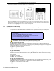
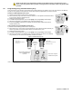
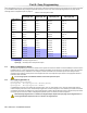


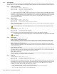
Table Of Contents
- Part 1: Introduction
- Part 2: Installation
- Part 3: Programming Methods
- Part 4: Access Codes
- Part 5: Zone Programming
- Part 6: Wireless Features
- Part 7: Arming and Disarming Options
- 7.1 Switch To Stay Arming
- 7.2 Stay Arming with Delay
- 7.3 Regular Arming Switches to Force Arming (Not to be used with UL Installations)
- 7.4 Restrict Arming on Battery Fail
- 7.5 Restrict Arming on Tamper Failure
- 7.6 Timed Auto-Arming
- 7.7 No Movement Auto-Arming
- 7.8 Auto-Arming Options (Not to be used with UL installations)
- 7.9 One-Touch Arming (Not to be used with UL installations)
- 7.10 Exit Delay
- 7.11 Bell Squawk On Arm/Disarm with Keypad
- 7.12 Bell Squawk On Arm/Disarm with Remote Control
- 7.13 No Exit Delay When Arming with Remote Control
- 7.14 No Exit Delay Beeps and No Bell Squawk When Stay Arming
- Part 8: Alarm Options
- Part 9: Reporting and Dialer settings
- 9.1 Reporting/Dialer (Enable/Disable)
- 9.2 Report Codes
- 9.2.1 Arming Report Codes
- 9.2.2 Special Arming Report Codes
- 9.2.3 Disarming Report Codes
- 9.2.4 Special Disarming Report Codes
- 9.2.5 Zone Alarm Report Codes
- 9.2.6 Zone Alarm Restore Report Codes
- 9.2.7 Special Alarm Report Codes
- 9.2.8 Zone Tamper Report Codes
- 9.2.9 Zone Tamper Restore Report Codes
- 9.2.10 System Trouble Report Codes
- 9.2.11 System Trouble Restore Codes
- 9.2.12 Special Reporting Codes
- 9.3 Monitoring Station Telephone Numbers
- 9.4 Partition Account Numbers
- 9.5 Reporting Formats
- 9.6 Pager Delay
- 9.7 Event Call Direction
- 9.8 Dialing Method
- 9.9 Pulse Ratio
- 9.10 Bell on Communication Failure
- 9.11 Dial Tone Delay
- 9.12 Maximum Dialing Attempts
- 9.13 Delay Between Dialing Attempts
- 9.14 Alternate Dial Option
- 9.15 Recent Close Delay
- 9.16 Auto Test Report
- 9.17 Closing Delinquency Timer
- 9.18 Power Failure Report Delay
- 9.19 Disarm Reporting Options
- 9.20 Zone Restore Report Options
- 9.21 Telephone Line Monitoring (TLM)
- Part 10: Programmable Outputs
- Part 11: System Settings
- 11.1 Hardware Reset
- 11.2 Installer Lock
- 11.3 Keypad Lockout Feature
- 11.4 Battery Charge Current
- 11.5 Partitioning
- 11.6 System Real-Time Clock
- 11.7 Clock Adjust
- 11.8 Keypad Tamper Supervision
- 11.9 Keypad Audible Trouble Warning
- 11.10 Confidential Mode
- 11.11 Installer Quick Functions Keys
- 11.12 PGM Modules Supervision
- 11.13 Printer Module Supervision
- 11.14 Zone Expansion Bus Module Supervision
- 11.15 Wireless Transmitter Low Battery Supervision
- 11.16 Wireless Transmitter Supervision Options
- 11.17 Reprogram All Expansion Modules
- Part 12: Settings for WinLoad Software
- Part 13: User Operation
- 13.1 Trouble Display
- 13.2 Programming Access Codes
- 13.3 Disarming & Deactivating an Alarm
- 13.4 Regular Arming
- 13.5 Stay Arming
- 13.6 Instant Arming
- 13.7 Force Arming (Not to be used with UL Installations)
- 13.8 Manual Bypass Programming
- 13.9 One-Touch Arming
- 13.10 Keyswitch Arming
- 13.11 Panic Alarms
- 13.12 Auto-Arming (Not to be used with UL installations)
- 13.13 Alarm Memory Display
- 13.14 Programming Chime Zones
- 13.15 Keypad Muting (Not to be used with UL installations)
- 13.16 Keypad Backlight (1686H and 1686V only)
- FCC Warnings
- Index

Spectra 1759MG 9
NOTE: The keypad can be ordered with or without an anti-tamper switch. If the keypad has no anti-
tamper switch, key [3] will be OFF by default. If the keypad has an anti-tamper switch, key [3] will be ON
by default.
3.4 Programming Using A Paradox Memory Key*
Copy the sections of one Spectra control panel into the Paradox Memory Key (PMC-3). Then copy the contents of the Memory
Key into as many Spectra control panels as needed. Each panel is programmed in less than 3 seconds.
Download to DESTINATION Control Panel
1) Remove AC and battery power from the control panel.
2) Place the Memory Key on the serial connector labeled
KEY of the Spectra Control Panel that is
to receive the contents of the Memory Key.
3) Reapply AC and battery power.
4) In Installer Programming Mode, enter section [900], then press [
ENTER] to acknowledge.
5) When the keypad emits a confirmation beep, remove the Memory Key.
6) Enter section [750] to reprogram the modules with the information downloaded from the
Paradox Memory Key.
Copy to Memory Key from SOURCE Control Panel
1) Remove AC and battery power from the control panel.
2) Place Memory Key on the serial connector labeled
KEY of the Spectra Control Panel that you
want to copy. Make sure the write protect jumper of the Memory Key is on.
3) Reapply AC and battery power.
4) In Installer Programming Mode, enter section [902], then press [
ENTER] to acknowledge.
5) When the keypad emits a confirmation beep, remove the Memory Key. Remove the Memory
Key’s jumper if you do not wish to accidentally overwrite its contents.
Figure 9: Paradox Memory Key
* Not investigated by UL
Jumper ON =
Read from and/or write to
memory key.
Paradox
Memory Key
PMC-3
Jumper OFF =
Write protected (read from
memory key only)
Insert Paradox Memory Key
onto the ‘MEMORY KEY’
connector.
Partial view of Spectra
1759MG control panel