
Installation Instructions
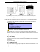
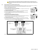
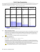


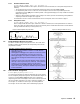
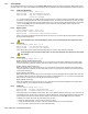
Table Of Contents
- Part 1: Introduction
- Part 2: Installation
- Part 3: Programming Methods
- Part 4: Access Codes
- Part 5: Zone Programming
- Part 6: Wireless Features
- Part 7: Arming and Disarming Options
- 7.1 Switch To Stay Arming
- 7.2 Stay Arming with Delay
- 7.3 Regular Arming Switches to Force Arming (Not to be used with UL Installations)
- 7.4 Restrict Arming on Battery Fail
- 7.5 Restrict Arming on Tamper Failure
- 7.6 Timed Auto-Arming
- 7.7 No Movement Auto-Arming
- 7.8 Auto-Arming Options (Not to be used with UL installations)
- 7.9 One-Touch Arming (Not to be used with UL installations)
- 7.10 Exit Delay
- 7.11 Bell Squawk On Arm/Disarm with Keypad
- 7.12 Bell Squawk On Arm/Disarm with Remote Control
- 7.13 No Exit Delay When Arming with Remote Control
- 7.14 No Exit Delay Beeps and No Bell Squawk When Stay Arming
- Part 8: Alarm Options
- Part 9: Reporting and Dialer settings
- 9.1 Reporting/Dialer (Enable/Disable)
- 9.2 Report Codes
- 9.2.1 Arming Report Codes
- 9.2.2 Special Arming Report Codes
- 9.2.3 Disarming Report Codes
- 9.2.4 Special Disarming Report Codes
- 9.2.5 Zone Alarm Report Codes
- 9.2.6 Zone Alarm Restore Report Codes
- 9.2.7 Special Alarm Report Codes
- 9.2.8 Zone Tamper Report Codes
- 9.2.9 Zone Tamper Restore Report Codes
- 9.2.10 System Trouble Report Codes
- 9.2.11 System Trouble Restore Codes
- 9.2.12 Special Reporting Codes
- 9.3 Monitoring Station Telephone Numbers
- 9.4 Partition Account Numbers
- 9.5 Reporting Formats
- 9.6 Pager Delay
- 9.7 Event Call Direction
- 9.8 Dialing Method
- 9.9 Pulse Ratio
- 9.10 Bell on Communication Failure
- 9.11 Dial Tone Delay
- 9.12 Maximum Dialing Attempts
- 9.13 Delay Between Dialing Attempts
- 9.14 Alternate Dial Option
- 9.15 Recent Close Delay
- 9.16 Auto Test Report
- 9.17 Closing Delinquency Timer
- 9.18 Power Failure Report Delay
- 9.19 Disarm Reporting Options
- 9.20 Zone Restore Report Options
- 9.21 Telephone Line Monitoring (TLM)
- Part 10: Programmable Outputs
- Part 11: System Settings
- 11.1 Hardware Reset
- 11.2 Installer Lock
- 11.3 Keypad Lockout Feature
- 11.4 Battery Charge Current
- 11.5 Partitioning
- 11.6 System Real-Time Clock
- 11.7 Clock Adjust
- 11.8 Keypad Tamper Supervision
- 11.9 Keypad Audible Trouble Warning
- 11.10 Confidential Mode
- 11.11 Installer Quick Functions Keys
- 11.12 PGM Modules Supervision
- 11.13 Printer Module Supervision
- 11.14 Zone Expansion Bus Module Supervision
- 11.15 Wireless Transmitter Low Battery Supervision
- 11.16 Wireless Transmitter Supervision Options
- 11.17 Reprogram All Expansion Modules
- Part 12: Settings for WinLoad Software
- Part 13: User Operation
- 13.1 Trouble Display
- 13.2 Programming Access Codes
- 13.3 Disarming & Deactivating an Alarm
- 13.4 Regular Arming
- 13.5 Stay Arming
- 13.6 Instant Arming
- 13.7 Force Arming (Not to be used with UL Installations)
- 13.8 Manual Bypass Programming
- 13.9 One-Touch Arming
- 13.10 Keyswitch Arming
- 13.11 Panic Alarms
- 13.12 Auto-Arming (Not to be used with UL installations)
- 13.13 Alarm Memory Display
- 13.14 Programming Chime Zones
- 13.15 Keypad Muting (Not to be used with UL installations)
- 13.16 Keypad Backlight (1686H and 1686V only)
- FCC Warnings
- Index

Spectra 1759MG 15
5.6.2 Standard 24Hr Fire Zone
Sections [001] to [005]: Zones 1 to 5, First Digit = 8
Whenever a Standard 24Hr Fire Zone opens, whether it is armed or disarmed, the control panel will generate the
following:
• The control panel can send the corresponding Alarm report code from sections [187] to [190].
• If a tamper/wiring fault occurs on a fire zone, the control panel can send a Fire Loop Trouble report code
programmed in section [206] to the monitoring station. The keypad will display a Fire Loop Trouble in its trouble
display (see page 42).
• Alarms are always audible regardless of other settings. Fire alarms generate an intermittent (pulsed) bell/siren
output signal as shown in Figure 11 on page 15.
For information on how to connect smoke detectors to the control panel, refer to Fire Circuits on page 6.
5.6.3 Delayed Fire Zone
Sections [001] to [005]: Zones 1 to 5, First Digit = 9
When a Delayed 24Hr Fire Zone opens, whether it is armed or disarmed, the control panel will react as shown in
Figure 12 on page 15. Delayed 24Hr Fire Zones are commonly used in residential homes where a smoke detector
often generates false alarms (i.e. burning bread, etc.).
5.7 Programming a Wireless Fire Zone
Fire zones cannot be assigned to expansion zones. As a result, when
installing a wireless smoke detector, the corresponding zone must be
programmed as follows:
5.8 Zone Partition Assignment
Sections [001] to [015]: Zones 1 to 15
The control panel provides the option of partitioning the security system
into two completely independent systems. As demonstrated in Figure 10
on page 13, sections [001] to [015] represent zones 1 through 15
respectively, where the second digit in each of these sections represents
the zone's partition assignment. The zone is assigned to Partition 1 if
second digit = 1, Partition 2 if second digit = 2, or both partitions is
second digit = 3. For more details, refer to Partitioning on page 36.
How Do I Program a Wireless Fire Zone?
1) Enter [5] in the Zone Definition to define it as a 24Hr Burglary
Alarm (see page 14).
2) Disable [4] and enable [5] in Zone Options to set the zone’s alarm
type to a pulsed Audible Alarm (see Figure 10 on page 13).
3) Disable [1] and [2] in Zone Options to disable the zone’s Auto
Zone Shutdown and Bypass Enabled features (see Figure 10 on
page 13).
4) Change the zone’s report code from a Burglary report code (Prog.
Value 11) to a Fire report code (Prog. Value 04). If using Ademco
Contact I.D., set the Contact ID Options from All Codes to
Programmable (section [136] option [3] = OFF) and then enter the
report code manually. See Spectra 1759MG Programming Guide
for more information.
Bell
Output
On
Off
Fire Alarm
Latched
0.5s 0.5s
1.
5s
Figure 11: Bell Output During Fire Alarm
Figure 12: Delayed 24Hr Fire Zone