
Installation Instructions


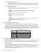


Table Of Contents
- Part 1: Introduction
- Part 2: Installation
- Part 3: Programming Methods
- Part 4: Access Codes
- Part 5: Zone Programming
- Part 6: Wireless Features
- Part 7: Arming and Disarming Options
- 7.1 Switch To Stay Arming
- 7.2 Stay Arming with Delay
- 7.3 Regular Arming Switches to Force Arming (Not to be used with UL Installations)
- 7.4 Restrict Arming on Battery Fail
- 7.5 Restrict Arming on Tamper Failure
- 7.6 Timed Auto-Arming
- 7.7 No Movement Auto-Arming
- 7.8 Auto-Arming Options (Not to be used with UL installations)
- 7.9 One-Touch Arming (Not to be used with UL installations)
- 7.10 Exit Delay
- 7.11 Bell Squawk On Arm/Disarm with Keypad
- 7.12 Bell Squawk On Arm/Disarm with Remote Control
- 7.13 No Exit Delay When Arming with Remote Control
- 7.14 No Exit Delay Beeps and No Bell Squawk When Stay Arming
- Part 8: Alarm Options
- Part 9: Reporting and Dialer settings
- 9.1 Reporting/Dialer (Enable/Disable)
- 9.2 Report Codes
- 9.2.1 Arming Report Codes
- 9.2.2 Special Arming Report Codes
- 9.2.3 Disarming Report Codes
- 9.2.4 Special Disarming Report Codes
- 9.2.5 Zone Alarm Report Codes
- 9.2.6 Zone Alarm Restore Report Codes
- 9.2.7 Special Alarm Report Codes
- 9.2.8 Zone Tamper Report Codes
- 9.2.9 Zone Tamper Restore Report Codes
- 9.2.10 System Trouble Report Codes
- 9.2.11 System Trouble Restore Codes
- 9.2.12 Special Reporting Codes
- 9.3 Monitoring Station Telephone Numbers
- 9.4 Partition Account Numbers
- 9.5 Reporting Formats
- 9.6 Pager Delay
- 9.7 Event Call Direction
- 9.8 Dialing Method
- 9.9 Pulse Ratio
- 9.10 Bell on Communication Failure
- 9.11 Dial Tone Delay
- 9.12 Maximum Dialing Attempts
- 9.13 Delay Between Dialing Attempts
- 9.14 Alternate Dial Option
- 9.15 Recent Close Delay
- 9.16 Auto Test Report
- 9.17 Closing Delinquency Timer
- 9.18 Power Failure Report Delay
- 9.19 Disarm Reporting Options
- 9.20 Zone Restore Report Options
- 9.21 Telephone Line Monitoring (TLM)
- Part 10: Programmable Outputs
- Part 11: System Settings
- 11.1 Hardware Reset
- 11.2 Installer Lock
- 11.3 Keypad Lockout Feature
- 11.4 Battery Charge Current
- 11.5 Partitioning
- 11.6 System Real-Time Clock
- 11.7 Clock Adjust
- 11.8 Keypad Tamper Supervision
- 11.9 Keypad Audible Trouble Warning
- 11.10 Confidential Mode
- 11.11 Installer Quick Functions Keys
- 11.12 PGM Modules Supervision
- 11.13 Printer Module Supervision
- 11.14 Zone Expansion Bus Module Supervision
- 11.15 Wireless Transmitter Low Battery Supervision
- 11.16 Wireless Transmitter Supervision Options
- 11.17 Reprogram All Expansion Modules
- Part 12: Settings for WinLoad Software
- Part 13: User Operation
- 13.1 Trouble Display
- 13.2 Programming Access Codes
- 13.3 Disarming & Deactivating an Alarm
- 13.4 Regular Arming
- 13.5 Stay Arming
- 13.6 Instant Arming
- 13.7 Force Arming (Not to be used with UL Installations)
- 13.8 Manual Bypass Programming
- 13.9 One-Touch Arming
- 13.10 Keyswitch Arming
- 13.11 Panic Alarms
- 13.12 Auto-Arming (Not to be used with UL installations)
- 13.13 Alarm Memory Display
- 13.14 Programming Chime Zones
- 13.15 Keypad Muting (Not to be used with UL installations)
- 13.16 Keypad Backlight (1686H and 1686V only)
- FCC Warnings
- Index

34 Reference & Installation Manual
With option [1] OFF, the control panel will send the Disarming report codes (see page 28) to the monitoring station every time the
system is disarmed. With option [1] ON, the control panel will send the Disarming report codes to the monitoring station when the
system is disarmed following an alarm.
9.20 Zone Restore Report Options
Section [132]: Zone Options
Option [6] OFF = Report On Bell Cut-Off (default)
Option [6] ON = Report On Zone Closure
With option [6] OFF, the 1759MG will send the Zone Alarm Restore report codes (see page 29) to the monitoring station when the
zone has returned to normal and the Bell Cut-Off Timer has elapsed (see page 25). With option [6] ON, the 1759MG will send the
Zone Alarm Restore report codes to the monitoring station as soon as the zone returns to normal or when the system is disarmed.
9.21 Telephone Line Monitoring (TLM)
When enabled, the system verifies the existence of a telephone line once every second. A line test failure occurs when the TLM
detects less than 3 volts for the period defined by the TLM Fail Timer. If the line test fails, the control panel’s
STATUS LED flashes
and generates one or more conditions as defined by the TLM settings below. These will be restored when the control panel
detects the telephone line again. Please note that when the dialer detects an incoming call, the TLM test will stop for 1 minute.
Section [135]: Dialer Options
[1] OFF / [2] OFF: TLM Disabled
[1] OFF / [2] ON: Trouble Only
Upon line test failure, a TLM Trouble will appear in the keypad’s Trouble Display (see page 42).
[1] ON / [2] OFF: Alarm If System Armed
Upon line test failure, a TLM Trouble will appear in the keypad’s Trouble Display (see page 42) and if the system is armed, the
control panel will generate an alarm.
[1] ON / [2] ON: Silent Alarm Becomes Audible
Upon line test failure, a TLM Trouble will appear in the keypad’s Trouble Display (see page 42) and causes a silent zone or silent
panic alarm to switch to audible.
9.21.1 TLM Fail Timer
Section [079]
016 to 255 x 2 seconds, Default = 32 seconds
If TLM does not detect the existence of a telephone line for the duration of this period, the control panel will generate
the condition(s) defined by the TLM options (see above).
Part 10: Programmable Outputs
A PGM is a programmable output that toggles to its opposite state (i.e. a normally open PGM will close) when a specific event has occurred
in the system. For example, a PGM can be used to reset smoke detectors, activate bells or strobe lights, open/close garage doors and
much more. When a PGM closes, the control panel supplies a ground to the PGM activating any device or relay connected to it. When a
PGM opens, the circuit opens from ground, therefore, cutting power to any devices connected to it.
PGM1
A programmable output that provides
up to 150mA.
Refer to
Alarm Relay and PGMs on page 4.
PGM2
PGM2 is a programmable output that can provide up to 1A. PGM2 is designed to be used as a Strobe Output. For information refer to PGM
Strobe Options on page 35. For connections, refer to Alarm Relay and PGMs on page 4.
Global PGM
The Global PGM allows you to use the control panel’s PGM Event List to activate PGMs located on a module or LCD keypad. For example, if
you enable a module’s “Follows Global PGM” option, the PGM on the module will activate whenever the event programmed in section [124]
occurs. Every PGM on every keypad and/or expansion bus module can be programmed to follow the event(s) defined by the Global PGM.
10.1 PGM Activation Event
Sections [120], [122], and [124]
This feature allows you to program the control panel to activate a PGM when a specific event occurs in the system. The PGM will
remain in its active state until the programmed PGM Deactivation Event occurs or when the PGM Delay period elapses (see
page 35). For the Event List see the PGM Table in the Spectra 1759MG Programming Guide. To program a PGM Activation Event: