759MG System Programming Guide Software Version 2.0 Default Installer Code 0000 / 000000 (see section [281] on page 18) Default System Master Code 1234 / 123456 (see section [301] on page 18) How Do I Enter Programming Mode? 1) 2) 3) 4) Press [ENTER]. Enter your [INSTALLER CODE]. Enter 3-digit [SECTION] you wish to program. Enter required [DATA].
Table of Contents Default Installer Code...................................................................................................................................................... 1 Default System Master Code .......................................................................................................................................... 1 How Do I Enter Programming Mode? ......................................................................................................................
Voice-assisted Arm/Disarm Bus Module (APR3-ADM2)............................................................................................... 34 8-Zone Expansion Bus Modules (SPC-ZX8 and APR3-ZX8) ...................................................................................... 35 Hardware Connections..................................................................................................................... 36 Single Zone Inputs ..............................................................
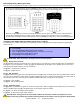
Data Display Mode (LED Keypads Only) View the section’s programming one digit at a time. Does not function with sections using Feature Select Programming. To access the Data Display Mode, press the [ENTER] key after entering a section and before entering any data. The three LEDs as indicated below will begin to flash indicating that you are in the Data Display Mode.
Zone Programming When programming zones, the zone assignments are dependent on where the detection devices are connected to in the system (see Zone Recognition Table). In installations that require using mostly the expansion inputs, refer to Reassign Keypad Zone 2 (see section [126] option [7] on page 12) and Reassign zones to expansion inputs (see section [126] option [8] on page 12). . Do not assign inputs from different modules to the same expansion input.
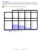
How Do I Program the Zones? 1) Press the [ENTER] key 2) Enter the [INSTALLER CODE] (Default: 0000 / 000000) 3) Enter 3-digit [SECTION] 4) Enter one digit from the Zone Definition table (see page 7) 5) Enter one digit from the Partition Assignment table (see page 7) 6) Select one or more options from the Zone Options table (see page 7) 7) Press the [ENTER] key Zone Definition Partition Assignment Zone Options Empty - Zone Disabled 1 - Entry Delay 1 2 - Entry Delay 2 3 - Follow 4 - Instant 5 - 24Hr Burgla
System Timers Section # [050] [051] [052] [053] [054] [055] [056] [057] [058] [059] [060] [061] [062] [063] [064] [065] [066] [067] [068] [069] [070] [071] [072] [073] [074] [075] [076] [077] [078] [079] [080] [081] [082] [083] [084] [085] [086] [087] [088] [089] [090] [091] [092] [093] [094] [095] [110] [111] [112] ___/___/___ ___/___/___ ___/___/___ ___/___/___ ___/___/___ ___/___/___ ___/___/___ ___/___/___ ___/___/___ ___/___/___ ___/___/___ ___/___/___ ___/___/___ ___/___/___ ___/___/___ Decimal Valu
Programmable Outputs Each PGM Deactivation event can be used as another start (activation) event if their respective PGM timer (see sections [066] to [068]) is programmed with a value other than 000. Example: section [120] = 05 03 02: this means PGM1 will activate whenever partition 2 is Stay Armed.
Event Group # Sub-Group # 09 = Button Pressed on Remote (see button option “D” on page 25) 01 to 08 = Remote Controls 1 to 8 99 = Any Remote Control 10 = Bypass Programming 01 to 48 = User Code Numbers 001 to 048 99 = Any User Code 11 = User Activated PGM 01 to 48 = User Code Numbers 001 to 048 (Partition 1 only) 99 = Any User Code 12 = Zone with Delay Transmission Option Enabled is Breached 01 to 15 = Zones 1 to 15 99 = Any Zone 13 = Arm with User Code 01 to 48 = User Code Numbers 001 to 048 99
Event Group # Sub-Group # 28 = System Trouble 01 = AC Loss: only after Power Failure Delay has elapsed (Partition 1 only) 02 = Battery Failure (Partition 1 only) 03 = Auxiliary current overload (Partition 1 only) 04 = Bell current overload (Partition 1 only) 05 = Bell disconnected (Partition 1 only) 06 = Timer Loss (Partition 1 only) 07 = Fire Loop Trouble (Partition 1 only) 08 = Future Use 09 = Module Fault (Partition 1 only) 10 = Printer Fault (Partition 1 only) 11 = Fail to Communicate (Partition 1 on
System Options Bold = Default Setting Section [126]: General Options Option OFF ON N Enter Access Code N Press a Key N Disabled [1] Confidential Mode [2] To exit Confidential Mode [3] Confidential Mode timer [4] PGM1 normal state [5] PGM2 normal state [6] Global PGM normal state [7] Reassign Keypad Zone 2* [8] Reassign zones to expansion inputs* N 2 minutes N Normally Open (N.O.) N Normally Open (N.O.) N Normally Open (N.O.
Bold = Default Setting Section [130]: Arming/Disarming Options Option [1] One-touch Regular Arming [2] One-touch Stay Arming [3] One-touch Force Arming [4] One-touch bypass programming [5] Restrict arming on battery failure [6] Restrict arming on Tamper failure [7] Bell Squawk on Arm/Disarm with keypad [8] Beep on exit delay OFF ON N Disabled N Enabled N Disabled N Enabled N Disabled N Enabled N Disabled N Enabled N Disabled N Enabled N Disabled N Enabled N Disabled N Enabled
Bold = Default Setting Section [133]: Partition 1 Options Option OFF ON N Disabled N Enabled N Disabled [1] Auto-arm on time [2] Auto-arm on no movement [3] Auto Arming = Regular or Stay [4] Switch to Stay Arming if no entry delay is opened [5] Stay Arming with Delay Partition 1 (Delay = [070]) N Regular Arming N Stay Arming N Disabled N Enabled N N/A N N/A N Disabled [6] to [8] Future use N Enabled N Enabled Section [134]: Partition 2 Options Option OFF ON N Disabled N Enable
Bold = Default Setting Section [137]: Event Call Direction Option [1] Call Telephone #1 for Arming/Disarming Report Codes [2] Call Telephone #2 for Arming/Disarming Report Codes [3] Call Telephone #1 for Alarm/Restore Report Codes [4] Call Telephone #2 for Alarm/Restore Report Codes [5] Call Telephone #1 for Tamper/Restore Report Codes [6] Call Telephone #2 for Tamper/Restore Report Codes [7] & [8] Future use OFF ON N Disabled N Enabled N Disabled N Disabled N Disabled N Disabled N Disa
Report Codes Ademco Slow, Silent Knight, SESCOA, Ademco Express and Pager Formats: Enter the desired 1- or 2-digit hex-value (0-F or 00-FF). Ademco “Programmable” Format: Enter the desired 2-digit hex values from the “Ademco Report Code List - Programmable” (see Appendix A on page 30). Also Note that entering FF will set the report code to the default Ademco Report Code.
Alarm Report Codes Alarm Restore Special [187]___/___Zone 01 ___/___Zone 02 ___/___Zone 03 ___/___Zone 04 [191]___/___Zone 01 ___/___Zone 02 ___/___Zone 03 ___/___Zone 04 [195]___/___Emergency Panic ___/___Auxiliary Panic ___/___Fire Panic ___/___Recent Closing [188]___/___Zone 05 ___/___Zone 06 ___/___Zone 07 ___/___Zone 08 [192]___/___Zone 05 ___/___Zone 06 ___/___Zone 07 ___/___Zone 08 [196]___/___Zone Shutdown ___/___Duress ___/___Keypad Lockout ___/___N/A [189]___/___Zone 09 ___/___Zone 10 ___
System Settings Section # Description [280] ___/___:___/___ SYSTEM REAL TIME CLOCK (HH:MM) [281] ___/___/___/___/___/___ INSTALLER CODE, DEFAULT: [282] ___/___/___ INSTALLER CODE LOCK, DEFAULT: 000 (147 TO LOCK, 000 TO UNLOCK) [301] ___/___/___/___/___/___ SYSTEM MASTER CODE, DEFAULT: 1234 / 123456 0000 / 000000 User Code Options System Master Code arms or disarm partitions using any arming method and can create, modify or delete any User Access Code.
Reprogram All Modules [750] After removing an expansion module from the communication bus, the control panel keeps the module’s programmed sections in memory. Therefore, if you add or replace a module you can re-program the module with the settings saved in the control panel. To do so, enter section [750] and press [ENTER]. The keypads will beep twice every second until the procedure is completed. Paradox Memory Key (PMC-3) [900] [902] DOWNLOAD FROM PARADOX MEMORY KEY TO DESTINATION CONTROL PANEL.
4-PGM Output Modules V2.0 Due to the APR3-PGM4’s Auto-recognition feature, it can be used with either the Spectra (V2.0 or higher), DGP-848 or DGP-NE96 control panel. When connected to the bus, the APR3-PGM4 automatically detects which control panel it is connected to and adjusts its internal communication parameters to function accordingly. Only one APR3-PGM4 can be connected to each Spectra control panel. Modules with the APR- prefix are compatible with Spectra (versions 2.0 and higher) and DGP-848.
Printer Module V2.0 Due to the APR3-PRT1’s Auto-recognition feature, it can be used with either the Spectra (V2.0 or higher), DGP-848 or DGP-NE96 control panel. When connected to the bus, the APR3-PRT1 automatically detects which control panel it is connected to and adjusts its internal communication parameters to function accordingly. Only one APR3-PRT1 can be connected to each Spectra control panel. Modules with the APR- prefix are compatible with Spectra (versions 2.0 and higher) and DGP-848.
Bold = Default Setting Section [553]: Serial and Parallel Port Setup Options Option [1] OFF ON N see table N see table N see table N see table N Disabled Serial port [2]&[3] Baud Rate Settings [2] [3] OFF OFF 1200 baud (default) APR-PRT1 2400 baud (default) APR3-PRT1 9600 baud ON OFF 2400 baud OFF ON 9600 baud 19200 baud ON ON 19200 baud 57600 baud [4] Parallel port [5] Off-line status ignored (parallel port only) [6] Paper empty status ignored (parallel port only) [7] Pri
Voice-assisted Arm/Disarm Bus Module V2.0 Due to InTouch’s Auto-recognition feature, it can be used with either the Spectra (V2.0 or higher), DGP-848 or DGP-NE96 control panels. When connected to the bus, InTouch automatically detects which control panel it is connected to and adjusts its internal communication parameters to function accordingly. Only one InTouch can be connected to each Spectra control panel. APR3-ADM2 can also be programmed using the WinLoad Software.
Wireless Features Do not cut, bend or alter 1759MG’s antennae and ensure that electrical wires do not cross over the antennae, as this may affect signal reception. Zone Assignment The serial number can be located on the inside of the transmitter or you can use the Serial Number Display feature (see page 24). Also, refer to Zone Recognition Table on page 6.
Remote Control User Assignment Section # [701] [702] [703] [704] [705] [706] [707] [708] Decimal Value ___/___/___(001-048 = user #) ___/___/___(001-048 = user #) ___/___/___(001-048 = user #) ___/___/___(001-048 = user #) ___/___/___(001-048 = user #) ___/___/___(001-048 = user #) ___/___/___(001-048 = user #) ___/___/___(001-048 = user #) Description remote control #1 - section [731]* remote control #2 - section [732]* remote control #3 - section [733]* remote control #4 - section [734]* remote control
Remote Control Assignment Enter the appropriate section and press any button on the remote control twice to assign the remote control. If you hear a rejection beep, an error has occurred or the remote control has already been assigned. To delete a remote control, enter the desired section and then press the [FORCE] button.
Zone Expansion Bus Modules Only one SPC/APR3-ZX4 or one SPC/APR3-ZX8 can be connected to each Spectra control panel. The following sections are for SPC-ZX4 version 1.0, APR3-ZX4 version 1.0, SPC-ZX8 version 1.0 and APR3-ZX8 version 2.0. Modules with the APR- prefix are compatible with Spectra (versions 2.0 and higher) and DGP-848. Modules with the APR3- prefix are compatible with Spectra (versions 2.0 and higher), DGP-848 and DGP-NE96.
User Operation Partitioning The Spectra system is equipped with a partitioning feature which can divide the alarm system into two distinct areas identified as Partition 1 and Partition 2. Partitioning can be used in installations where shared security systems are more practical, such as an office/warehouse building. If the system is not partitioned, all User Codes and features will be recognized as belonging to Partition 1.
Programming Chime Zones This feature allows users to program which zones will be Chime Enabled. A Chime Enabled zone will cause the keypad to emit a rapid intermittent beep tone (BEEP-BEEP-BEEP-BEEP) advising the user every time it is opened. Each keypad must be Chime Programmed separately. Keypad chimes must be re-programmed if the system suffers a total power loss (16-zone LED and LCD Keypads only).
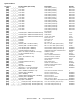
Appendix A - Ademco CID Report Code List (Prog.) If using the Ademco Contact ID Programmable code format, enter the 2-digit hexadecimal value from the table below (Prog. Value) into sections [160] to [213] to program the desired report codes. To enter a 0 value press the [FORCE] key. CID# Reporting Code Prog. Value MEDICAL ALARMS - 100 100 Medical Alarm 01 CID# Reporting Code Prog. Value CID# Reporting Code Prog.
Appendix B - Ademco CID Report Code List (All Codes) System Event Default Contact ID Report Code when option [3] is on in section [136] System Event Default Contact ID Report Code when option [3] is on in section [136] Arming with Master Code (##) 3 4A1 - Close by user Auxiliary supply trouble 1 3AA - System trouble Arming with User Code (##) 3 4A1 - Close by user Bell output current limit 1 321 - Bell 1 Arming with Keyswitch (##) 3 4A9 - Keyswitch Close Bell absent 1 321 - Bell 1 Auto Armin
Bus Module Connections Printer Module (APR3-PRT1) Press the “PRINT TEST” switch to perform a print test C A RX LED reserved for future use B Spectra 1759MG Control Panel F Not Used Communication Bus D E Connecting the PGM Output A Green “Locate” LED: Remains illuminated during power up B Red “Watchdog” LED: Flashes to indicate proper operation. If there is a communication failure, the red LED will flash ON for one second and OFF for one second.
4-PGM Output Module (APR3-PGM4) Red “Watchdog” LED: Status: flashes once per second to indicate proper operation. Flash 1 second on and 1 second off: The module is experiencing a communication failure with the control panel. To Spectra 1759MG control panel External Power Supply (Recommended: Paradox PSW817 1.
Voice-assisted Arm/Disarm Bus Module (APR3-ADM2) Remove AC and battery power from the control panel before adding the APR3-ADM2 module to the system. Do not connect the APR3-ADM2 more than 76m (250ft) from the control panel. Only one APR3ADM2 can be connected per Spectra control panel. Green "PULSE"LED: Monitors the dialer. The LED will illuminate when the dialer is in use. When the dialer is not being used, the LED will remain off. Red “WATCHDOG” LED: Flashes once every second = normal.
8-Zone Expansion Bus Modules (SPC-ZX8 and APR3-ZX8) Red “WDG” LED: Flash once every sec. = normal. Flash 1 sec. on & 1 sec. off = Trouble and/or communication failure. Not Used Inset 2 Not Used Refer to the Spectra 1759MG Reference & Installation Manual about connecting devices to the Expansion Input Terminals. Inset 1 Inset 1: Connecting the PGM output Communication Spectra 1759MG Bus control panel Inset 2: Anti-Tamper Switch Connection Input terminal Z1 can be used as an anti-tamper switch input.
Hardware Connections Single Zone Inputs Connecting Fire Circuits, Keyswitches and PGMs Program the PGM with the “[PG]/[FNC1] Key was pressed” Activation Event so that the smoke detectors can be reset by pressing the [PG] or [FNC1] key. See Event Group # 5 on page 9. Fire Circuits Keyswitch PGM 4-Wire Installation Control Panel Terminals All 4-wire smoke detectors must be connected using the daisy chain configuration. Programming a Wireless Fire Zone Fire zones cannot be assigned to expansion zones.
Alarm Relay and PGM Connections Alarm Relay (5A) can be programmed to follow the BELL output or the Global PGM AUX+ External power supply External Power Supply Any device such as a strobe light or siren PGMs When the device connected to a PGM is powered by: AUX+ terminal = must not exceed 700mA External power supply = PGM1 cannot exceed 150mA PGM2 cannot exceed 1A If power supply's current limit is less than that of the PGM it is connected to, then the current consumption cannot exceed the power supply's
Spectra 1759MG PCB Layout "STATUS" LED: Flash once every second = normal Flashes ON 1 second and OFF 1 second = trouble "RX" LED: Flashes quickly when receiving signals from wireless devices. Always ON = panel is using phone line Fast flash 4 seconds after power up = installer lock enabled Antennae Paradox Memory Key (PMC-3) Warning: Do not cut, bend or alter the antennae and ensure that electrical wires do not cross over the antennae, as this may affect signal reception.
Warranty Paradox Security Systems Ltd. (“Seller”) warrants its products to be free from defects in materials and workmanship under normal use for a period of one year. Except as specifically stated herein, all express or implied warranties whatsoever, statutory or otherwise, including without limitation, any implied warranty of merchantability and fitness for a particular purpose, are expressly excluded.
For technical support in Canada or the U.S., call 1-800-791-1919 for English or 1-866-912-0600 for French, Monday to Friday from 8:00 a.m. to 8:00 p.m. EST. For technical support outside Canada and the U.S., call 00-1-450-491-7444, Monday to Friday from 8:00 a.m. to 8:00 p.m. EST. Please feel free to visit our website at www.paradox.ca. 780 Industriel Blvd., Saint-Eustache (Quebec) J7R 5V3 CANADA Tel.: (450) 491-7444 Fax: (450) 491-2313 www.paradox.