
Programming Guide
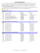
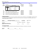
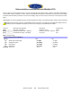
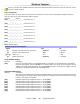
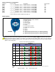
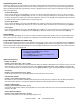
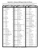
Table Of Contents
- Default Installer Code
- Default System Master Code
- How Do I Enter Programming Mode?
- Decimal and Hexadecimal Programming Table
- Trouble Display
- Data Display Mode (LED Keypads Only)
- Configuring the 1686H, 1686V and 1689 Keypads (V2.0 or higher)
- Zone Programming
- System Timers
- Programmable Outputs
- System Options
- Communication Settings
- Report Codes
- System Settings
- User Code Options
- Reprogram All Modules
- Paradox Memory Key (PMC-3)
- 4-PGM Output Modules V2.0
- Printer Module V2.0
- Voice-assisted Arm/Disarm Bus Module V2.0
- Wireless Features
- Zone Expansion Bus Modules
- User Operation
- Appendix A - Ademco CID Report Code List (Prog.)
- Appendix B - Ademco CID Report Code List (All Codes)
- Bus Module Connections
- Hardware Connections

Spectra 1759MG - 27 - Programming Guide
Zone Expansion Bus Modules
Only one SPC/APR3-ZX4 or one SPC/APR3-ZX8 can be connected to each Spectra control panel. The following sections
are for SPC-ZX4 version 1.0, APR3-ZX4 version 1.0, SPC-ZX8 version 1.0 and APR3-ZX8 version 2.0.
Modules with the APR- prefix are compatible with Spectra (versions 2.0 and higher) and DGP-848. Modules with the
APR3- prefix are compatible with Spectra (versions 2.0 and higher), DGP-848 and DGP-NE96.
Bold = Default Setting
PGM Programming (SPC-ZX8 and APR3-ZX8 Only)
The PGM will only activate or deactivate 100mS after the selected event occurs. The PGM Deactivation event can be used
as another activation event if the PGM Timer (section [655]) is programmed with a value other than 000. The system will
ignore the PGM if it has been programmed to follow the Global PGM (option [3] in section [650]). Only PGM events from the
table below can be used.
Section # Decimal Value (000-255) Description Default Value
[655] ___/___/___ seconds (000 = follow deactivation event)
PGM1 TIMER 5 sec.
Section # Event Group # Sub-Group # Partition #
[656] PGM1 Activation Event ___/___ ___/___ ___/___
[657] PGM1 Deactivation Event ___/___ ___/___ ___/___
Section [650]: Options
Option
OFF ON
[1]
EOL (end-of-line) resistors for hardwire modules N No EOL N Use EOL Resistors
[2]
Zone Expansion Module tamper recognition N Disabled N Z1 becomes tamper input
[3]
PGM1 on SPC/APR3-ZX8 follows Global PGM
programmed in sections [124] & [125]
N Disabled N Enabled
[4]
to
[8]
Future Use N N/A N N/A
Section [651]: Zone Assignment
Option See Zone Recognition Table on page 6. OFF ON
[1] Input Z1 =Expansion Input 1 N Disabled N Enabled
[2] Input Z2 =Expansion Input 2 N Disabled N Enabled
[3] Input Z3 =Expansion Input 3 N Disabled N Enabled
[4] Input Z4 =Expansion Input 4 N Disabled N Enabled
[5] Input Z5 (
SPC/APR3-ZX8 only) =Expansion Input 5 N Disabled N Enabled
[6] Input Z6 (
SPC/APR3-ZX8 only) =Expansion Input 6 N Disabled N Enabled
[7] Input Z7 (
SPC/APR3-ZX8 only) =Expansion Input 7 N Disabled N Enabled
[8] Input Z8 (
SPC/APR3-ZX8 only) =Expansion Input 8 N Disabled N Enabled
Event Group # Sub-Group # Partition #
For SPC-ZX8:
60 = Hardwire Zone Opened
61 = Hardwire Zone Closed
62 = Hardwire Tamper Opened
63 = Hardwire Tamper Closed
For APR3-ZX8:
60 = Hardwire Zone/Hardwire Tamper Opened
61 = Hardwire Zone/Hardwire Tamper Closed
01 = Expansion Input 1 - Section [651] - [1]
02 = Expansion Input 2 - Section [651] - [2]
03 = Expansion Input 3 - Section [651] - [3]
04 = Expansion Input 4 - Section [651] - [4]
05 = Expansion Input 5 - Section [651] - [5]
06 = Expansion Input 6 - Section [651] - [6]
07 = Expansion Input 7 - Section [651] - [7]
08 = Expansion Input 8 - Section [651] - [8]
99 = Any zone expansion bus module input
Not used; enter 00