
Programming Guide
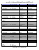
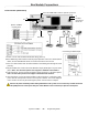
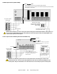
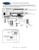
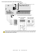
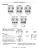
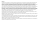

Table Of Contents
- Default Installer Code
- Default System Master Code
- How Do I Enter Programming Mode?
- Decimal and Hexadecimal Programming Table
- Trouble Display
- Data Display Mode (LED Keypads Only)
- Configuring the 1686H, 1686V and 1689 Keypads (V2.0 or higher)
- Zone Programming
- System Timers
- Programmable Outputs
- System Options
- Communication Settings
- Report Codes
- System Settings
- User Code Options
- Reprogram All Modules
- Paradox Memory Key (PMC-3)
- 4-PGM Output Modules V2.0
- Printer Module V2.0
- Voice-assisted Arm/Disarm Bus Module V2.0
- Wireless Features
- Zone Expansion Bus Modules
- User Operation
- Appendix A - Ademco CID Report Code List (Prog.)
- Appendix B - Ademco CID Report Code List (All Codes)
- Bus Module Connections
- Hardware Connections

Spectra 1759MG - 33 - Programming Guide
4-PGM Output Module (APR3-PGM4)
4-zone expansion Bus Module (SPC-ZX4 and APR3-ZX4)
Red “Watchdog” LED:
Status: flashes once per second to indicate proper operation.
Flash 1 second on and 1 second off: The module is experiencing a communication
failure with the control panel.
External Power Supply
(Recommended: Paradox
PSW817 1.75A Switching
Power Supply)
To Spectra 1759MG
control panel
Not Used
Any device such as a garage
door opener, light or siren
Communication
Bus
Remove AC and battery from the control panel before adding the 4-PGM Output Module to the system. Do
not connect the APR3-PGM4 more than 76m (250ft) from the control panel. Only one APR3-PGM4 can be
connected per Spectra control panel.
Not Used
Red “WDG” LED:
Status = Flashes to indicate proper operation.
Flash 1 sec. on & 1 sec. off = Trouble and/or
communication failure.
Connect the detection devices to the
module's input terminals exactly as shown
in the Spectra 1759MG Reference &
Installation Manual.
Not Used
Spectra 1759MG
control panel
Communication
Bus
Remove AC and battery power from the control panel before connecting the module to the
communication bus. Do not connect the APR3-ZX4 or SPC-ZX4 more than 76m (250ft) from the
control panel. Only one APR3-ZX4 or one SPC-ZX4 can be connected per Spectra control panel.
Input terminal Z1 can be used
as an anti-tamper switch input
Option [2]: Section [650]
Connecting the Anti-
Tamper Switch