
Programming Guide
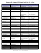
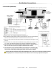
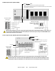
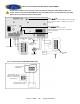
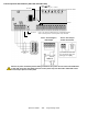
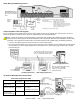
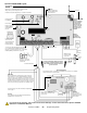
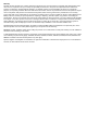

Table Of Contents
- Default Installer Code
- Default System Master Code
- How Do I Enter Programming Mode?
- Decimal and Hexadecimal Programming Table
- Trouble Display
- Data Display Mode (LED Keypads Only)
- Configuring the 1686H, 1686V and 1689 Keypads (V2.0 or higher)
- Zone Programming
- System Timers
- Programmable Outputs
- System Options
- Communication Settings
- Report Codes
- System Settings
- User Code Options
- Reprogram All Modules
- Paradox Memory Key (PMC-3)
- 4-PGM Output Modules V2.0
- Printer Module V2.0
- Voice-assisted Arm/Disarm Bus Module V2.0
- Wireless Features
- Zone Expansion Bus Modules
- User Operation
- Appendix A - Ademco CID Report Code List (Prog.)
- Appendix B - Ademco CID Report Code List (All Codes)
- Bus Module Connections
- Hardware Connections

Spectra 1759MG - 34 - Programming Guide
Voice-assisted Arm/Disarm Bus Module (APR3-ADM2)
Green "PULSE"LED:
Monitors the dialer. The LED will illuminate when the dialer
is in use. When the dialer is not being used, the LED will
remain off.
Red “WATCHDOG” LED:
Flashes once every second = normal.
Flashes 1 second on & 1 second off = trouble and/or
communication failure.
Communication
Bus
Ground
clamp
Cold water pipe
grounding
Household
telephone
Refer to Inset 1
To Spectra 1759MG
control panel
Spectra 1759MG
Dialer
Not Used
Inset 1: Connecting the APR3-ADM2 PGM Output
Partial view of the
APR3-ADM2
External Power Supply
(Recommended: Paradox
PSW817 1.75A Switching
Power Supply)
Any device such as a garage
door opener, light or siren
Remove AC and battery power from the control panel before adding the APR3-ADM2 module to the
system. Do not connect the APR3-ADM2 more than 76m (250ft) from the control panel. Only one APR3-
ADM2 can be connected per Spectra control panel.