
Programming Guide
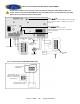
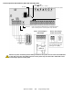
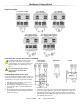
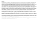

Table Of Contents
- Default Installer Code
- Default System Master Code
- How Do I Enter Programming Mode?
- Decimal and Hexadecimal Programming Table
- Trouble Display
- Data Display Mode (LED Keypads Only)
- Configuring the 1686H, 1686V and 1689 Keypads (V2.0 or higher)
- Zone Programming
- System Timers
- Programmable Outputs
- System Options
- Communication Settings
- Report Codes
- System Settings
- User Code Options
- Reprogram All Modules
- Paradox Memory Key (PMC-3)
- 4-PGM Output Modules V2.0
- Printer Module V2.0
- Voice-assisted Arm/Disarm Bus Module V2.0
- Wireless Features
- Zone Expansion Bus Modules
- User Operation
- Appendix A - Ademco CID Report Code List (Prog.)
- Appendix B - Ademco CID Report Code List (All Codes)
- Bus Module Connections
- Hardware Connections

Spectra 1759MG - 35 - Programming Guide
8-Zone Expansion Bus Modules (SPC-ZX8 and APR3-ZX8)
Red “WDG” LED:
Flash once every sec. = normal.
Flash 1 sec. on & 1 sec. off = Trouble and/or communication failure.
Not Used
Inset 2
Not Used
Inset 1
Refer to the Spectra 1759MG Reference & Installation Manual
about connecting devices to the Expansion Input Terminals.
Communication
Bus
Spectra 1759MG
control panel
Inset 1: Connecting the
PGM output
Inset 2: Anti-Tamper
Switch Connection
Input terminal Z1 can be used
as an anti-tamper switch input.
Option [2]: Section [650]
Remove AC power and battery before adding a module to the system. Do not connect the APR3-ZX8
or SPC-ZX8 more than 76m (250ft) from the control panel. Only one SPC-ZX8 or APR3-ZX8 can be
connected per Spectra control panel.