
Programming Guide

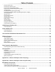

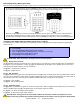
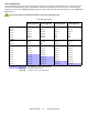
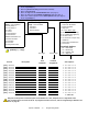
Table Of Contents
- Default Installer Code
- Default System Master Code
- How Do I Enter Programming Mode?
- Decimal and Hexadecimal Programming Table
- Trouble Display
- Data Display Mode (LED Keypads Only)
- Configuring the 1686H, 1686V and 1689 Keypads (V2.0 or higher)
- Zone Programming
- System Timers
- Programmable Outputs
- System Options
- Communication Settings
- Report Codes
- System Settings
- User Code Options
- Reprogram All Modules
- Paradox Memory Key (PMC-3)
- 4-PGM Output Modules V2.0
- Printer Module V2.0
- Voice-assisted Arm/Disarm Bus Module V2.0
- Wireless Features
- Zone Expansion Bus Modules
- User Operation
- Appendix A - Ademco CID Report Code List (Prog.)
- Appendix B - Ademco CID Report Code List (All Codes)
- Bus Module Connections
- Hardware Connections

Spectra 1759MG - 5 - Programming Guide
Data Display Mode (LED Keypads Only)
View the section’s programming one digit at a time. Does not function with sections using Feature Select Programming.
Configuring the 1686H, 1686V and 1689 Keypads (V2.0 or higher)
The keypad’s zone number, EOL definition and anti-tamper switch are programmed through the keypad’s programming
mode. To do so:
PLEASE NOTE: After two minutes, the keypad exits programming mode.
Key [1] - Keypad Zone Selection
Key [1] determines whether the keypad’s zone is Keypad Zone 1 or Keypad Zone 2. When key [1] is OFF (not illuminated),
the keypad’s zone is Keypad Zone 1. When key [1] is ON (illuminated), the keypad’s zone is Keypad Zone 2. Refer to the
Zone Recognition Table on page 6 for more information.
Key [1] OFF - Keypad Zone 1 (default)
Key [1] ON - Keypad Zone 2
Key [2] - EOL Definition
Key [2] determines the keypad zone’s EOL definition. When key [2] is OFF (not illuminated), EOL is disabled and the keypad
zone uses the on-board EOL resistor. When key [2] is ON (illuminated), EOL is enabled and the keypad zone requires that an
external EOL resistor be connected (refer to Spectra 1759MG PCB Layout on page 38 for more details).
Key [2] OFF - EOL disabled
Key [2] ON - EOL enabled (default)
Key [3] - On-Board Tamper
Key [3] enables or disables the keypad’s on-board anti-tamper switch. When key [3] is OFF (not illuminated), the anti-tamper
switch is disabled. When key [3] is ON (illuminated), the anti-tamper switch is enabled.
Key [3] OFF - On-board anti-tamper switch disabled
Key [3] ON - On-board anti-tamper switch enabled
PLEASE NOTE: The keypad can be ordered with or without an anti-tamper switch. If the keypad has no anti-
tamper switch, key [3] will be OFF by default. If the keypad has an anti-tamper switch, key [3] will be ON by default.
How Do I Configure The Keypad?
1) Press [
ENTER]
2) Enter your [
INSTALLER CODE] (default: 0000 / 000000)
3) Press the [
PG] (1686H/V) / [FNC1] (1689) key and hold it for 3 seconds.
4) Press the desired key ([1] to [3]. See below)
5) Press [
ENTER] to exit programming mode
To access the Data Display Mode, press the [ENTER] key after entering a section and before entering any data. The
three LEDs as indicated below will begin to flash indicating that you are in the Data Display Mode.
Each time the
[ENTER] key is pressed, the keypad will display the next digit in the current section and will continue
through all the following sections one digit at a time without changing the programmed values. Not available for
sections using the Multiple Feature Select Method. Press the [
CLEAR] key at any time to exit the Data Display Mode.