. MGSP Installation Guide 32-Zone Wireless Security Systems MG5075 v1.01 MG5050 & MG5000 v4.90 MG5050E v7.14 4 to 32-Zone Expandable Security Systems SP5500, SP6000 & SP7000 v7.14 SP4000 v5.23 SP65 v5.
Table of Contents Introduction ............................................................................ 5 Keyswitch Programming .....................................................35 Features ................................................................................................................................ 5 MG5075 Additional Features ........................................................................................ 5 System Overview ................................................
Pulse Ratio ......................................................................................................................... 53 Maximum Dialing Attempts ....................................................................................... 53 Maximum Dialing Attempts - VDMP3 ..................................................................... 53 Delay Between Dialing Attempts .............................................................................. 53 Switch to Pulse on 5th Attempt .........
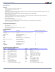
Magellan & Spectra SP • Installation Guide Introduction Features • • • • • • • • • • • • • 32 zones (any of which can be wireless or keypad zones) 32 users and 32 remote controls (one per user) In-field upgradeable Menu-driven programming for the Installer, Master, and Maintenance codes.
Magellan & Spectra SP • Installation Guide Specifications MG5000 / MG5050 / MG5075 MG5000/MG5050: 16.5 VAC (50 or 60Hz) minimum 20 VA (40 VA recommended) MG5075: Internal Power Supply (75W) 110 - 220 VAC, 1A, 50-60 Hz Wall Plug (60W) 15Vdc MG5000: 1.2A(Max.), 85 mA (Idle) MG5050: 1.2A(Max.), 95 mA (Idle) MG5075: 1A (Max.), 220 mA (Idle) MG5000/MG5050: 600 mA typical, 700 mA maximum, fuseless shutdown at 1.1A MG5075: 15V, 2.
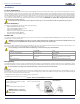
Magellan & Spectra SP • Installation Guide Installation Location and Mounting Before mounting the metal box, push the five white nylon mounting studs into the back of the box. Pull all cables into the cabinet and prepare them for connection before mounting the circuit board into the back of the cabinet. For the MG5075, if tamper is required, remove the PCB from the plastic enclosure prior to mounting.
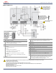
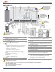
Magellan & Spectra SP • Installation Guide MG5000 PCB Layout Do not cut, bend, or alter the antenna, and ensure that electrical wires do not cross over it, as this may affect signal reception. To provide maximum lightning protection we strongly recommend having separate earth connections for the dialer and zone ground terminals. Disconnect telephone line before servicing.
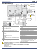
Magellan & Spectra SP • Installation Guide MG5050 / MG5050 EN PCB Layout Do not cut, bend, or alter the antenna, and ensure that electrical wires do not cross over it, as this may affect signal reception. To provide maximum lightning protection we strongly recommend having separate earth connections for the dialer and zone ground terminals. Disconnect telephone line before servicing.
Magellan & Spectra SP • Installation Guide MG5075 PCB Layout Do not cut, bend, or alter the antenna, and ensure that electrical wires do not cross over it, as this may affect signal reception. To provide maximum lightning protection we strongly recommend having separate earth connections for the dialer and zone ground terminals. Disconnect telephone line before servicing. OR If using the wall plug, ensure that the wires are secured to avoid detaching from the panel.
Magellan & Spectra SP • Installation Guide SP4000 PCB Layout Disconnect telephone line before servicing. To provide maximum lightning protection we strongly recommend having separate earth connections for the dialer and zone ground terminals. 1 Paradox Memory Key (PMC5) 2 EBUS (J3) and Dialer (J4) used with: • VDMP3 Plug-in Voice Module for voice reporting • PCS Series Communicator Module 3 Status LED: • Flash once every second: Normal • Flashes ON 1 sec. and OFF 1 sec.
Magellan & Spectra SP • Installation Guide SP5500 PCB Layout Disconnect telephone line before servicing. To provide maximum lightning protection we strongly recommend having separate earth connections for the dialer and zone ground terminals. 1 PGM +/- trigger not supported by the SP5500 2 LEDs 3 4 5 6 7 Status LED: • Flash once every second: Normal • Flashes ON 1 sec. and OFF 1 sec.
Magellan & Spectra SP • Installation Guide SP6000 PCB Layout Disconnect telephone line before servicing. To provide maximum lightning protection we strongly recommend having separate earth connections for the dialer and zone ground terminals. 1 PGM Trigger: This jumper allows you to choose whether the solid state relay PGMs are ground (-), or give out 12V (+) 2 LEDs 3 4 5 6 7 Status LED: • Flash once every second: Normal • Flashes ON 1 sec. and OFF 1 sec.
Magellan & Spectra SP • Installation Guide SP7000 PCB Layout Disconnect telephone line before servicing. To provide maximum lightning protection we strongly recommend having separate earth connections for the dialer and zone ground terminals. 1 PGM Trigger: This jumper allows you to choose whether the solid state relay PGMs are ground (-), or give out 12V (+) 2 LEDs 3 4 5 6 7 Status LED: • Flash once every second: Normal • Flashes ON 1 sec. and OFF 1 sec.
Magellan & Spectra SP • Installation Guide PCB Metal Box Installation The crosses and dotted line represent the PCB mounting location. If you need specific dimensions, contact Paradox Distributor Support. For UL recommended installation for the MG5000 only, place the PCB one notch lower than the mounting location. MG5000 (8x10”) MG5000 (11x11”) Tamper Kit (TK278) MG5050 / MG5050EN (11x11”) For EN compliancy use the Tamper Kit TK278 (MG5050EN and SP Series).
Magellan & Spectra SP • Installation Guide SP5500 (8x10”) SP6000 (11x11”) SP7000 (11x11”) 16
Magellan & Spectra SP • Installation Guide Auxiliary Power Terminals The auxiliary power supply terminals can be used to power motion detectors, keypads and other modules or accessories in the security system. A fuseless circuit protects the power supply against current overload and automatically shuts down if the current exceeds 1.1A or 3A for the MG5075. If this occurs, the Maximum Auxiliary Current failure will appear in the keypad’s trouble display (See “Trouble Display” on page 63).
Magellan & Spectra SP • Installation Guide Single Zone Inputs Detection devices such as motion detectors and door contacts are connected to the control panel's zone input terminals. Figure 3 demonstrates single zone input terminal connections recognized by the panel. Once connected, the associated zone's parameters must be defined.
Magellan & Spectra SP • Installation Guide Advanced Technology Zone (ATZ) Connections The ATZ feature is a software oriented feature that enables two detection devices to be installed per hardwired input terminal. Each detection device has its own zone, displays its zone status on the keypad and sends its own alarm codes. Fire zones cannot be doubled.
Magellan & Spectra SP • Installation Guide Fire Circuits When a zone is programmed as a fire zone, the zone becomes normally open and requires an EOL resistor. If a line short occurs or if the smoke detector becomes active, whether the system is armed or disarmed, the control panel will generate an alarm.
Magellan & Spectra SP • Installation Guide Programming Methods BabyWare Software for Windows Program the control panels remotely or on-site using the BabyWare Software (V2.80 or higher) for Windows®. For more information, contact your local Paradox Distributor or visit our web site at paradox.com. If you are using the BabyWare software, you must program the features (See “Settings for BabyWare Software” on page 61).
Magellan & Spectra SP • Installation Guide Configuring the Keypad Zone Number How Do I Configure The Keypad? Press [ENTER] Enter your [INSTALLER CODE] (default: 0000 / 000000) or [MAINTENANCE CODE] (empty by default) Press [ ] and hold for three seconds Enter the desired zone number key (K32+,K32LCD+: 2-digit entry 01 to 32, K10V/H: 1-digit entry 1 to 0(10)) Press [ENTER] to save and exit programming mode Press [CLEAR] to erase data without saving Press [CLEAR]+[CLEAR] to exit programming mode without savi
Magellan & Spectra SP • Installation Guide LCD Keypad Labels Input Keys Special Function Keys Alphanumeric Key Input Key Function [1] A/B/C [stay] Insert space [2] D/E/F [sleep] Delete [3] G/H/I [arm] Delete whole entry [4] J/K/L [off] Toggle numeric/alphanumeric keys M/N/O Toggle lower case/upper case [5] [byp] P/Q/R Special characters [6] [mem] [7] S/T/U [8] V/W/X [9] Y/Z Label Sections Label Sections [181] to [212] 32 Zone Labels [341] to [356] 16 PGM Labels [511] t
Magellan & Spectra SP • Installation Guide Hebrew Keypad Letter Assignment Hebrew Special Characters Catalogue Greek Keypad Letter Assignment Key Press key once Press key twice 032 048 064 080 096 112 160 176 192 208 224 240 033 049 065 081 097 113 161 177 193 209 225 241 034 050 066 082 098 114 162 178 194 210 226 242 035 051 067 083 099 115 163 179 195 211 227 243 036 052 068 084 100 116 164 180 196 212 228 244 037 053 069 085 101 117
Magellan & Spectra SP • Installation Guide Russian Keypad Letter Assignment Russian Special Characters Catalogue 25
Magellan & Spectra SP • Installation Guide Access Codes The control panel supports the following access codes: Installer Code [397]: Maintenance Code [398]: System Master Code [399]: Master Code 1: Master Code 2: 29 User Codes: Used to program all control panel settings except user access codes. The Maintenance code is similar to the Installer code. It can be used to enter programming mode, which allows you to program all the features, options and commands except for the panel’s communication settings.
Magellan & Spectra SP • Installation Guide Partition 2 Assignment Sections [404] to [432]: User Codes 004 to 032 Option [2] OFF= Deny access to partition 2 (default) Option [2] ON= User code has access to partition 2 If the system is partitioned (See “Partitioning” on page 58), user codes with this option enabled can arm and disarm partition 2. If the system is not partitioned, the control panel ignores this option.
Magellan & Spectra SP • Installation Guide StayD Mode Overview • NOTE: StayD is automatically enabled when a path is programmed to a keypad. When deleting a wireless keypad from the system, the corresponding path zones will also be deleted. StayD simplifies your life and makes it safer by protecting you 24 hours a day, 7 days a week without ever having to disarm the system - even when entering an armed area.
Magellan & Spectra SP • Installation Guide Zone Programming When programming zones, the zone assignments are dependent on the designation of the wireless transmitters, assignment of keypad zones, and the detection devices that are connected to the panel. For wireless assignment, See “Wireless Transmitter Programming” on page 36 or the Installer Quick Menu of the programming guide. For keypad assignment, See “Configuring the Keypad Zone Number” on page 22.
Magellan & Spectra SP • Installation Guide Entry Delay 2 (Full Arm) Zones Sections [001] to [032]: Zones 1 to 32, First Digits = 04 Upon regular arming, the zone is Entry Delay 2 (See “Entry Delay 2 Zones” on page 29). Upon Stay/Sleep arming, the zone is bypassed by the system. See Zone Definition Status on page 32 for any exceptions.
Magellan & Spectra SP • Installation Guide Delayed Fire Zones Sections [001] to [032]: Zones 1 to 32, First Digits = 12 When a Delayed 24Hr. Fire zone opens, whether it is armed or disarmed, the control panel will react as shown in Figure 10. Delayed 24Hr. Fire zones are commonly used in residential homes where a smoke detector often generates false alarms (i.e., burning bread, etc.). Fire alarms generate an intermittent (pulsed) bell/siren output signal as shown in Figure 9 above.
Magellan & Spectra SP • Installation Guide 24 Hr. Freeze Zones Sections [001] to [032]: Zones 1 to 32, First Digits = 21 When a 24Hr. Freeze zone opens, whether it is armed or disarmed, the control panel will immediately generate an alarm. This alarm is defined by the alarm type, configured in Zone Programming under zone options [4] and [5]. See Alarm Types on page 33. The SIA FSK and CID reporting formats include specific report codes to identify the alarm as a Freeze alarm. 24Hr.
Magellan & Spectra SP • Installation Guide Auto Zone Shutdown Sections [001] to [032] = Zones 1 to 32 Option [1] OFF= Auto Zone Shutdown Disabled Option [1] ON= Auto Zone Shutdown Enabled for selected zone (default) If, in a single armed period, the number of alarms generated by a zone with the Auto Zone Shutdown option enabled exceeds the number defined by the Auto Zone Shutdown Counter, the control panel will no longer generate an alarm for that zone.
Magellan & Spectra SP • Installation Guide Force Zones Sections [001] to [032]: Zones 1 to 32 Option [8] OFF= Force Zone Disabled Option [8] ON= Selected Zone is Force Enabled (default) Any open Force Zones at the time of arming will be considered deactivated by the control panel. If during this period a deactivated zone is closed, the control panel will revert that zone to active status. Consequently, the control panel will generate an alarm if the zone is breached.
Magellan & Spectra SP • Installation Guide Keyswitch Programming Keyswitch Numbering On-board hardwire control panel zones only. Keyswitch Numbering allows you to assign any hardwired input in the system to any of the 32 keyswitch zones in the control panel. UL Note: Do not use keyswitches in UL Listed systems. Keyswitch Definitions Keyswitch Definitions determine how a keyswitch is used. Maintained Keyswitch On-board hardwire control panel zones only.
Magellan & Spectra SP • Installation Guide Wireless Features The control panel(s) allows for the addition of up to thirty-two fully supervised wireless transmitters, and up to thirty-two programmable remote controls. Wireless Transmitter Programming The programming of the wireless transmitters (detectors and door contacts) is accomplished in two steps: 1. Assign the wireless transmitter to the control panel. 2. Program the zones.
Magellan & Spectra SP • Installation Guide RF Module Supervision Timer Settings Section [706]: Supervision Options Option [1] OFF= Check-in supervision interval is every 24 hours (default) Option [1] ON= Check-in supervision interval is every 80 minutes Option [1] defines the time period that the control panel will expect a check-in status signal from its assigned wireless transmitters.
Magellan & Spectra SP • Installation Guide Programming the Remote Control Buttons Sections [611] to [642]: Remote Controls 1 to 32 respectively. Each remote control can be programmed to perform up to 4 different actions. Each digit in sections [611] to [642] represents a button or combination of buttons. Digits 1 through 4 can be programmed, while digits 5 through 8 are reserved for future use and must be defined as empty (reminder: [SLEEP] = empty). How Do I Program the Remote Control’s Buttons? 1.
Magellan & Spectra SP • Installation Guide Wireless Keypad Options Section [588]: Wireless Keypad Options If enabled, the panel can wait for each of its assigned wireless transmitters to send a status signal within a specified time to confirm their presence and functionality.
Magellan & Spectra SP • Installation Guide Viewing the Repeater’s Signal Strength Sections [548] to [549] Once the repeaters have been installed and assigned to the control panel, the signal strength of each repeater can be verified in sections [548] to [549]. Section [548] is the viewer for repeater 1 and section [549] is the viewer for the repeater 2. Sometimes moving the repeater or control panel by a small amount will greatly increase the signal reception.
Magellan & Spectra SP • Installation Guide Section [552] (Repeater 1) and Section [562] (Repeater 2): Wireless Repeater Options Enable or disable the repetition of zone signals in these sections. Enabling these options for zones means that the repeater will retransmit any signals relevant to them.
Magellan & Spectra SP • Installation Guide Section [554] (Repeater 1) and Section [564] (Repeater 2): Wireless Repeater Options Enable or disable the repetition of zone signals in these sections. Enabling these options for zones means that the repeater will retransmit any signals relevant to them.
Magellan & Spectra SP • Installation Guide Section [556] (Repeater 1) and Section [566] (Repeater 2): Wireless Repeater Options Enable or disable the repetition of 2WPGM signals in these sections. Enabling these options for 2WPGMs means that the repeater will retransmit any signals relevant to them.
Magellan & Spectra SP • Installation Guide Arming and Disarming Options Switch to Stay Arming if no Entry Delay is opened Section [741]: Partition 1, Section [742] = Partition 2 Option [5] OFF= Switch to Stay Arming Disabled (default) Option [5] ON= Switch to Stay Arming Enabled If a user Regular arms a partition, but does not exit through (open and close) an entry delay zone during the exit delay, the control panel can be programmed to switch from Regular arming to Stay arming.
Magellan & Spectra SP • Installation Guide Restrict Arming on Wireless Supervision Trouble Section [703]: Arming/Disarming Options Option [7] OFF= Permit arming on wireless supervision failure (default) Option [7] ON= Restrict arming on wireless supervision failure If this option is enabled, the control panel will not arm the system if the control panel detects a wireless supervision trouble on one or more zones.
Magellan & Spectra SP • Installation Guide One-Touch Arming (Not to be used with UL installations) Section [703]: Options [1] to [3] Option [1] ON = Press & hold the [ARM] key for One-touch Regular Arming. Option [2] ON = Press & hold the [STAY] key for One-touch Stay Arming. Option [3] ON = Press & hold the [SLEEP] key for One-touch Sleep Arming. The One-touch arming features allow users to arm the system without having to enter any access codes.
Magellan & Spectra SP • Installation Guide Alarm Options Bell Cut-Off Timer Section [747] = Partition 1, [748] = Partition 2 000 = Disabled, 001 to 255 minutes, Default = 4 minutes, 5 minutes minimum for ULC installations After an audible alarm, the bell or siren will stop upon disarming of the partition or when the Bell Cut-Off Timer has elapsed, whichever comes first. Recycle Alarm After the Bell Cut-Off Timer and the Recycle Delay have elapsed, the control panel will re-verify the zone status.
Magellan & Spectra SP • Installation Guide Tamper Supervision on Panel (MG5075 only) Section [700]: Supervision Options Option [8] OFF= Panel tamper supervision disabled Option [8] ON= Panel tamper supervision enabled (default) When the control panel detects a tamper, the control panel can generate an alarm or trouble, unless the Tamper Supervision is disabled.
Magellan & Spectra SP • Installation Guide Reporting and Dialer settings The following section explains all the features and options that must be programmed in order for your security system to properly report system events to a monitoring station. When an event (e.g. zone in alarm) occurs in the system, the control panel verifies if a report code was programmed in the section corresponding to the event (except Ademco Contact ID “All Codes”).
Magellan & Spectra SP • Installation Guide System Trouble Report Codes Section [865] to [869] When the system generates one of the instances listed below, the control panel can send the appropriate report code to the monitoring station identifying the type of system trouble. Section [865] • N/A • AC Failure: The control panel has detected a loss of AC power. Transmission of this report code can be delayed. • Battery Failure: Backup battery is disconnected or battery voltage is low.
Magellan & Spectra SP • Installation Guide Clear Reporting Codes Section [966]: Clear Reporting Codes Option [1] OFF= Clear zone reporting codes Option [1] ON= Clear zone reporting codes (default) Option [2] OFF= Clear user reporting codes Option [2] ON= Clear user reporting codes (default) Option [3] OFF= Clear arm/disarm/alarm reporting codes Option [3] ON= Clear arm/disarm/alarm reporting codes (default) Option [4] OFF= Clear trouble reporting codes Option [4] ON= Clear trouble reporting codes (default)
Magellan & Spectra SP • Installation Guide Reporting Formats Section [810]: 1st digit = Format for Phone #1, 2nd digit = Format for Phone #2 The panel can use a number of different reporting formats and each monitoring station telephone number can be programmed with a different reporting format.
Magellan & Spectra SP • Installation Guide If the Alternate Dial option is enabled, the control panel will dial the programmed backup telephone number (if enabled) after every failed attempt. If no backup telephone number is programmed, the control panel will never report to the backup telephone number. Example: The system is armed and zone 1 has been breached causing an alarm. If options [5] and [7] are OFF and option [6] is ON in section [802], the control panel will attempt to communicate with MSTN 2.
Magellan & Spectra SP • Installation Guide Recent Closing Delay Section [838] 000 = Disabled, 001 to 255 seconds, Default = Disabled If after having armed the system, an alarm is generated within the period defined by the Recent Close Delay, the control panel will attempt to transmit the Recent Close report code programmed in section [863].
Magellan & Spectra SP • Installation Guide Zone Restore Report Options Section [801]: Zone Options Option [2] OFF= Report On Bell Cut-Off (default) Option [2] ON= Report On Zone Closure With option [2] OFF, the panel will send the Zone Alarm Restore report codes to the monitoring station when the zone has returned to normal and the Bell Cut-Off Timer has elapsed.
Magellan & Spectra SP • Installation Guide Programmable Outputs PGM is a programmable output that toggles to its opposite state (i.e. a normally open PGM will close) when a specific event has occurred in the system. For example, a PGM can be used to activate bells or strobe lights, open/close garage doors and much more. When a PGM activates, the control panel triggers any device or relay connected to it. The control panel includes two/four onboard PGMs. It can support up to a total of 16 PGMs.
Magellan & Spectra SP • Installation Guide When armed, the PGM will pulse once every 30 seconds. Option [6] OFF= PGM Pulse on any alarm disabled (default) Option [6] ON= PGM Pulse on any alarm enabled This option sets the PGMs to pulse on any alarm. Option [7] OFF= PGM Pulse on any alarm Partition 1(default) Option [7] ON= PGM Pulse on any alarm Partition 2 Program PGMs to pulse during an alarm for either partition.
Magellan & Spectra SP • Installation Guide System Settings Version Number Display Enter section [980] to view the version number of the panel. The first digit will appear. Press [ENTER] to scroll through each consecutive digit (the keypad will beep twice after every digit in the version number). Once the version number has been fully displayed, an acknowledgment beep (3 beeps) will sound and the first digit will be displayed again.
Magellan & Spectra SP • Installation Guide Installer Function Keys To access the Installer Function keys, press: [ENTER]+[INSTALLER CODE]+[MEM] = Test Report: Send the “Test Report” report code programmed in section [875] to the monitoring station. [ENTER]+[INSTALLER CODE]+[STAY] = Cancel Communication: Cancels all communication with BabyWare software or with the monitoring station until the next reportable event.
Magellan & Spectra SP • Installation Guide Display Entry Delay on LCD keypad (K32LCD+) Section [701]: General System Options Option [7] OFF= Display entry delay on LCD keypad Option [7] ON= Display entry delay on LCD keypad (default) When this option is enabled the panel will display entry delays on the K32LCD+ keypad modules.
Magellan & Spectra SP • Installation Guide Settings for BabyWare Software Note: BabyWare has not been verified by UL. Panel Answer Options The following two options define how the control panel answers an incoming call from a computer using the BabyWare Software for Windows®.
Magellan & Spectra SP • Installation Guide Automatic Event Buffer Transmission Section [900]: Dialer Options Option [2] OFF= Auto Event Buffer Transmission Disabled (default) Option [2] ON= Auto Event Buffer Transmission Enabled When the event buffer reaches 90% capacity, the control panel will make two attempts to establish communication with a PC using the BabyWare software by calling the PC Telephone Number programmed in section [915]. The BabyWare software must be in Wait to Dial mode.
Magellan & Spectra SP • Installation Guide User Operation Alarm Display If an alarm has occurred on a zone, the respective zone LED will flash, the [MEM] key will light up, and the zones will be stored in memory. These respective LEDs will continue to flash until disarming even if the zones are restored. To exit this mode and switch to live display mode before disarming, press the [CLEAR] key. Once the system is disarmed, the zones’ LEDs will turn off, while the [MEM] key remains lit.
Index Numerics 24 Hr. Burglary Zones ............................................................................................................ 31 24 Hr. Buzzer ............................................................................................................................. 31 24 Hr. Freeze Zones ................................................................................................................ 32 24 Hr. Gas Zones ...................................................................
G Number of Rings .....................................................................................................................60 Numbers .....................................................................................................................................53 Ground .......................................................................................................................................... 7 H Hardware Reset ..............................................................
Test Report ..................................................................................................................... 50 Report Code, Special Alarm Auto Zone Shutdown ................................................................................................. 49 Auxiliary Panic ............................................................................................................... 49 Duress ..............................................................................................
Magellan & Spectra SP • Installation Guide 68
Magellan & Spectra SP • Installation Guide 69
Magellan & Spectra SP • Installation Guide 70
The whole Paradox team wishes you a successful and easy installation. We hope this product performs to your complete satisfaction. Should you have any questions or comments, please contact us at support@paradox.com. Additional information can be found on our website www.paradox.com/support Printed in Canada - 12/2019 PARADOX.