
Installation Guide


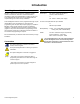
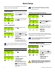
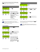
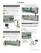
Table Of Contents
- Introduction
- About Magellan and this Manual
- Conventions
- Specifications
- Quick Setup
- Installation
- AC Power
- Backup Battery Pack
- Telephone Line Connections
- Programmable Outputs (PGMs)
- Hardwire Zone Connections
- WinLoad Connection
- UIP-256 Universal In-Field Programmer Connection
- X10 Transmitter Connection
- Connecting a Paradox Memory Key (PMC-3)
- Location and Mounting
- Connecting the Radio Antenna
- Programming Methods
- WinLoad Installer Upload/Download Software
- Programming Using the Built-in Keypad
- Programming Using a Paradox Memory Key
- User Codes
- User Code Length
- Installer Code
- Maintenance Code
- System Master Code
- Duress Code
- Zone Programming
- Zone Programming Overview
- Zone Definitions
- Zone Options
- Zones 15 and 16 become Hardwire Zones
- EOL (End-Of-Line) Zones
- Wireless Programming
- Assigning Wireless Zone Transmitters
- Assigning Wireless Doorbells to the Console
- Deleting Assigned Wireless Transmitters
- Viewing Wireless Transmitter Signal Strength
- Assigning Remote Controls
- Programming the Remote Control’s Buttons
- Arming and Disarming
- Regular Arming Switches to Stay Arming
- Regular Arming Switches to Force Arming
- Stay Arming Switches to Force Arming
- Timed Auto-Arming
- No Movement Auto-Arming
- Auto-Arming Options
- One-Touch Arming
- Exit Delay
- Bell Squawk on Arm/Disarm with Remote Control
- No Exit Delay when Arming with Remote Control
- Exit Delay Termination
- Follow Zone Switches to Entry Delay 2
- Closing Delinquency Timer
- Alarm Options
- Bell Cut-off Timer
- Wireless Transmitter Supervision Options
- Tamper Recognition Options
- Check-in Supervision Options
- Panic Alarms
- Reporting and Dialer Settings
- Report Codes
- Console Telephone Numbers
- Console Account Number
- Reporting Formats
- Event Call Direction
- Delay Between Dialing Attempts
- Alternate Dial Option
- Force Dial Option
- Dialing Method
- Pulse Ratio
- Switch to Pulse Dialing on 5th Attempt
- Telephone Line Monitoring (TLM)
- Recent Close Delay
- Auto-Test Report
- Power Failure Report Delay
- Disarm Reporting Options
- Zone Restore Report Options
- Programmable Outputs
- PGM Activation Event
- PGM Deactivation Event
- PGM Delay
- PGM Normal State
- PGM X10 Option
- System Settings
- Software Reset
- Installer Lock
- Console Tamper Supervision
- Console Audible Trouble Warning
- FM Tuner Option
- Daylight Savings Time
- AC Power Failure Warning
- The Trouble Display
- WinLoad Software Settings
- Panel Answer Options
- Panel Identifier
- PC Password
- PC Telephone Number
- Call Back Feature
- Appendix 1: Ademco Contact ID Report Code List
- Index

Paradox Magellan Systems 3
Introduction
About Magellan and this Manual
Magellan is designed for fast and easy installation. Simply
remove it from the box, mount the console and wireless
transmitters, apply power and Magellan is ready to protect your
home. Magellan has already been pre-programmed with the
required settings for a basic security installation.
Some of Magellan’s features can be programmed through a quick
Installer Menu (menu programming) or through section
programming. Use the quick setup chapter (page 4) to install the
Magellan console quickly and with the basic programming
required for a standard security application. All other chapters
(pages 6 to 33) are for advanced section programming. These
other chapters provide more in-depth and precise information if
more advanced programming is required.
We recommend that you read this entire manual before you begin
installation.
Conventions
Specifications
Power input: AC*:
9
Vac, 1A/9VA transformer or
16.5Vac, 20VA transformer
or
DC: 12Vdc to 18Vdc power supply
Current consumption:With AC input: 600mA
or
With DC input: 400mA
Backup Battery: 7.2Vdc, 1.8 to 2.0Ah NiMH rechargeable
battery pack (order # 0780100178)
PGMs: Two N.O. solid-state relays (not polarized)
Internal resistance - 169 (max.)
Max. current consumption - 50mA
* It is recommended that you use a 9Vac 1A/9VA transformer
to power the Magellan console. The console will generate
less heat when connected to a 9Vac transformer than when
connected to a 16.5Vac transformer.
This symbol designates a reference to another
section, manual or guide.
This symbol designates either a warning or important
information.
This symbol designates a reminder or suggestion.
[
DATA
] =
- Text shown in this manner designates data or
programming information that is entered through the
console’s keypad.
- Text shown in this manner can also designate a
specific key that has to be pressed.