
User's Manual

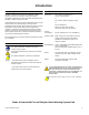
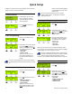
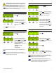
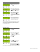
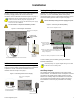
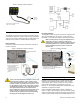
Table Of Contents
- Introduction
- About Magellan and this Manual
- Conventions
- Specifications
- Quick Setup
- Installation
- AC Power
- DC Power
- Backup Battery Pack
- Auxiliary Output
- Telephone Line Connections
- Programmable Outputs (PGMs)
- Hardwire Zone Connections
- WinLoad Connection
- UIP-256 Universal In-Field Programmer Connection
- X10 Transmitter Connection (MG-6160 only)
- Connecting a Paradox Memory Key (PMC-3)
- Location and Mounting
- Connecting the Radio Antenna (MG-6160 only)
- Programming Methods
- WinLoad Installer Upload/Download Software
- Programming Using the Built-in Keypad
- Programming Using a Paradox Memory Key
- User Codes
- User Code Length
- Installer Code
- Maintenance Code
- System Master Code
- Duress Code
- Zone Programming
- Zone Programming Overview
- Zone Definitions
- Zone Options
- Zones 31 and 32 Become Hardwire Zones
- EOL (End-Of-Line) Zones
- Assigning Wireless Zone Transmitters
- Assigning Wireless Doorbells to the Console
- Deleting Assigned Wireless Transmitters
- Viewing Wireless Transmitter Signal Strength
- Assigning Remote Controls
- Programming the Remote Control’s Buttons
- Assigning Wireless Keypads
- Assigning Wireless Repeaters
- Wireless Repeater Options
- Arming and Disarming
- Regular Arming Switches to Stay Arming
- Regular Arming Switches to Force Arming
- Stay Arming Switches to Force Arming
- Timed Auto-Arming
- No Movement Auto-Arming
- Auto-Arming Options
- One-Touch Arming
- Exit Delay
- Bell Squawk on Arm/Disarm with Remote Control
- No Exit Delay when Arming with Remote Control
- Exit Delay Termination
- Follow Zone Switches to Entry Delay 2
- Closing Delinquency Timer
- Stay Arm Siren Delay
- Alarm Options
- Bell Cut-off Timer
- Wireless Transmitter Supervision Options
- Check-in Supervision Options
- Tamper Recognition Options
- Wireless PGM Supervision Options
- Wireless Keypad Supervision Options
- Wireless Repeater Supervision Options
- Wireless PGM Console Supervision Options (Follow Alarm/Follow Bell)
- Backup Alarm Reporting Option
- Panic Alarms
- Reporting and Dialer Settings
- Report Codes
- Console Telephone Numbers
- Console Account Number
- Reporting Formats
- Event Call Direction
- Delay Between Dialing Attempts
- Alternate Dial Option
- Force Dial Option
- Dialing Method
- Pulse Ratio
- Switch to Pulse Dialing on 5th Attempt
- Telephone Line Monitoring (TLM)
- Recent Close Delay
- Auto-Test Report
- Power Failure Report Delay
- Disarm Reporting Options
- Zone Restore Report Options
- RF Jamming Supervision
- Programmable Outputs
- Assigning PGMs
- Setting PGM Function
- Onboard PGM Activation Event
- Onboard PGM Deactivation Event
- Onboard PGM Delay
- PGM Normal State (Onboard Only)
- PGM X10 Option (MG-6160 Only / Onboard Only)
- Wireless PGM Activation Event
- Wireless PGM Deactivation Event
- Wireless PGM Delay
- System Settings
- Software Reset
- Installer Lock
- Console Tamper Supervision
- Console Audible Trouble Warning
- FM Tuner Option (MG-6160 only)
- Daylight Savings Time
- AC Power Failure Warning
- The Trouble Display
- WinLoad Software Settings
- Panel Answer Options
- Panel Identifier
- PC Password
- PC Telephone Number
- Call Back Feature
- Appendix 1: Automatic Report Code List
- Appendix 2: Ademco Contact ID Report Code List
- Index

8 Reference & Installation Manual
Figure 4: Auxiliary Output Connection
Telephone Line Connections
The Magellan console can be connected to a telephone line by
connecting the telephone company’s wires directly to Magellan’s
dialer or by connecting a standard 4-pin RJ-11 cable between the
LINE plug of the console to a standard telephone wall jack.
Direct Connect
Connect the telephone line through a RJ31X jack as shown in
Figure 5 on page 8.
Figure 5: Telephone Line Direct Connect
For UL compliant installations, the Magellan console must
be able to seize the telephone line and place a call in a non-
medical emergency situation. It must be able to do this
even if other equipment (telephones, answering machines,
computer modems, etc.) already has the line in use. To do
so, the Magellan console must be connected to a properly
installed RJ31X jack that is in series with and ahead of all
other equipment attached to the same telephone line.
Proper installation is depicted in the diagram below. If you
have any questions concerning these instructions, you
should consult your telephone company about installing
the RJ31X jack and the Magellan console for you.
Line Plug Connect
The Magellan console can also be connected to a telephone line
via its on-board
LINE plug. See Figure 6 on page 8 for more
information on connecting the telephone line using this method.
When connecting via the LINE plug, if the telephone line is
shared and it is busy (i.e. someone is talking on the
telephone) the console will be unable to communicate with
the Monitoring Station. It is recommended that the Direct
Connect method (see page 8) be used to connect the
telephone line.
Figure 6: Line Plug Connection
Programmable Outputs (PGMs)
Magellan comes equipped with one 100mA solid-state PGM
output and one low powered open-collector; Max. handling
current 50mA. When a specific event occurs in the system, a
PGM can be programmed to activate lights, garage door
openers, etc. See Programmable Outputs on page 34 for more
information on programming PGMs.
Connect Magellan’s PGM outputs as shown in Method 1 in
Figure 7 on page 9. Since Magellan does not come with a power
supply, an external power supply must be employed to power the
circuit. The PGM outputs can be either Normally Open (N.O.) or
Insert the device’s wires into the
AUX
AND C terminals.
Devices
such as a
light, etc.
To connect the telephone line:
1. Connect a RJ31X to the
R-
1,
T-1, RING and TIP
terminals as shown at right.
2. Connect the telephone
company wires and the
home telephone to the
RJ31X.
Back view of the Magellan
console.
4-pin
RJ-11
cable
Back view of the Magellan console.
1
2
1. Insert one end of the 4-pin RJ-11 cable into the
LINE plug of the Magellan console.
2. Insert the other end of the RJ-11 cable into a
standard telephone wall plug.